5 Main Aspects of Gold Finger PCB Specification in Manufacturing Process
By:PCBBUY 02/25/2022 10:25

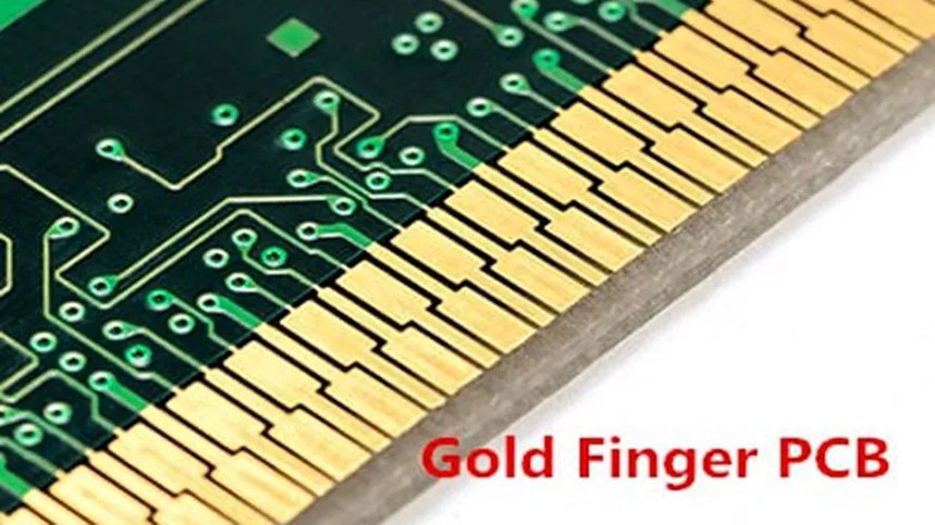
Have you found out that the edges of PCB gold fingers are in slope forms? Well, the procedure of beveling allows sharp, square edges to turn into slopes. In the case of PCBs or printed circuit boards, the beveling process completes the surface finish. The beveling process of the gold fingers of a PCB gets initiated after completing the disposition of solder masks.
The process of PCB gold finger beveling is unavoidable in terms of making insertions quicker and more effortless. Unless the gold finger beveling is completed, insertions will be more difficult than usual. If you are going to learn more knowledge of gold finger PCB, please check and read the content below.

How are gold fingers applied?
Gold fingers can be used for many various things. And they use depending on the designer’s purpose. There are some common applications of gold fingers as the follows:
1. Provide an interconnection point for transferring network data;
2. Connect external components to the PCB prototype;
3. A place for attaching specialized adapters or daughter boards;
4. Serve as an audio adapter
How are gold fingers used in PCB?
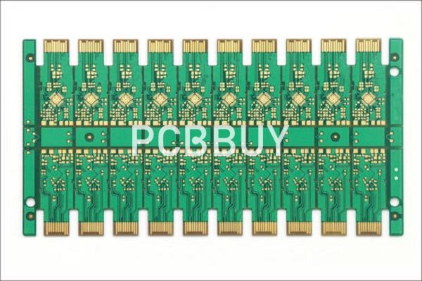
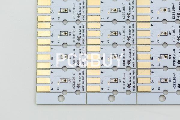
Gold fingers are used as connecting contacts between two adjoining PCBs. Aside from its conductivity, the purpose of the gold is to protect the connecting edges from wear over many uses. Due to the strength of hard gold at its specified thickness, gold fingers make it possible for a PCB to be connected, disconnected and reconnected up to 1,000 different times in a corresponding slot.
The functions of gold fingers are multi-purpose. With any given computer setup, you will see a number of peripherals that connect with the computer itself thanks to PCB gold fingers. Some of the most widespread uses of gold fingers include the following:
Interconnection points: When a secondary PCB connects to the main motherboard, it is done through one of several female slots, such as a PCI, ISA or AGP slot. Through these slots, the gold fingers conduct signals between a peripheral device or an internal card and the computer itself.
Special adapters: Gold fingers make it possible to add numerous performance enhancements to a personal computer. Through secondary PCBs that slot perpendicular into the motherboard, a computer can deliver enhanced graphics and hi-fidelity sound. Since these cards are seldom unattached and reattached, the gold fingers generally outlast the card itself.
External connections: The outer peripherals that have been added to a computer station are connected to the motherboard with PCB gold fingers. Devices such as speakers, subwoofers, scanners, printers and monitors are all plugged into specific slots behind the computer tower. These slots, in turn, attach to PCBs that connect to the motherboard.
For the corresponding device to work, its own card must connect to a power source. The fingers and corresponding slots on the motherboard make it all possible. Gold fingers provide module PCBs the power to operate and deliver modern-day functionality to users of remote and stationary computing devices.

The flexibility of the PCB system, whereby different slots connect different types of cards, makes it possible to upgrade the same computer periodically over five or ten years. Every time a sound or graphics card is updated, you can remove the pre-existing card from your motherboard and replace it with the new and improved model. Through each update, the PCB gold fingers remain the universal connecting contact.
What are the design specifications of gold fingers in PCB?
1. The internal PCB layer towards the edge of PCB must be free of copper to prevent exposure during chamfering.
2. It is not recommended to include PTH within 1mm of gold finger.
4. Keep a distance of at least 0.5mm between the gold finger and the circuit board outline.
5. Any compromise of the standard spacing values can lead to PCB weakness and failure.
6. Do not use anti welding or screen printing near the golden finger.
7. The gold finger shall be placed at the position with the PCB center facing outward.
The IPC has set some standards for the production of PCB gold fingers. IPC standards are summarized as follows:
· Chemical composition: in order to maximize the rigidity of the edge of PCB gold finger, the gold plating should contain 5% to 10% cobalt.
· Thickness: coating thickness shall be in the range of 2 to 50 microinches.
· Appearance test: the appearance inspection is carried out through a magnifying glass. The contact edge shall be smooth, the surface shall be clean and free of excessive coating such as nickel.
· Tape test: carry out this test to check the adhesion of gold plating on the contact. In this test, a tape is fixed to the contact edge and removed. In the next step, check the tape for traces of plating. If any gold is visible on the tape, the coating is not considered adequate for continuous injection and ejection.
Industry Category


