How to Improve Manufacturing Process with 7 PCB Heat Dissipation Techniques?
By:PCBBUY 09/26/2021 09:45

It’s really essential to do the heat regulation during the PCB manufacturing process. Care must be taken in choosing how to design and layout PCBs to prevent heat from accumulating in certain regions, which over time could cause catastrophic failures, perhaps even causing injury. To avoid failures or circuit malfunctions, designers should aim at producing PCBs that operate and remain within safe temperature limits.
In this article, we are going to provide all the PCB heat information for all the readers. If you are interested in the PCB heat dissipation techniques, please check and read the content for more professional knowledge.

What is the importance of PCB heat dissipation techniques?
It shouldn’t come as a surprise that electronics that require more power to operate will generate more heat. Components like voltage regulators, microcontrollers, and power transistors are all known to heat up when the load current increases.
Electronic components are all built to operate within a finite temperature range. If the surrounding temperature exceeds the upper limit, the components can break down. Even if it doesn’t break, the excessive heat will negatively affect the component’s performance.
When electronic components are exposed to excessive heat over a prolonged period, their lifespan shortens. If you’re negligent in your utilization of PCB heat dissipation techniques, you’ll soon face the issues related to premature component failures.
What are 7 main PCB heat dissipation techniques?
1. Identifying thermal and high-current traces
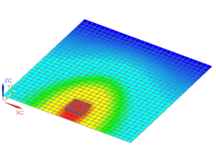
To fabricate a thermally stable PCB, thermal effects must be studied during the designing phase itself. The first step in thermal design is to identify the hotspots. Thermal modeling or thermal simulation techniques are used to find hotspots. Also, current flow analysis must be done along with it, because high-current traces cause heat generation.
The proper geometrical arrangement of components and high-current traces enables even distribution of heat. High-current traces must be routed away from thermally sensitive components such as sensors and Op-amps.

2. Use wider traces for reduce heat
Copper traces that conduct high currents build up heat. Therefore, it is important to increase the width of the trace to maximize heat dissipation to the air. Doing so also reduces the thermal resistance of the trace and reduces heat spots.
3. PCB thermal vias design
You can turn a PCB into an onboard heat sink by incorporating thermal via arrays over copper-filled areas, as shown above. The idea behind doing so is to have heat flowing from components to the copper area and dissipating through the air from the vias. Usually, thermal via arrays are used for power management modules and components with thermal pads.
When implementing thermal via arrays, remember that it needs to have a reasonably large diameter, in the region of 0.1 mm, for the heat to be dissipated effectively. Also, ensure the vias are not thermal-relief pads but padded holes that are connected to the copper area at all sides. Increasing the number of thermal vias further helps with heat dissipation.
4. Proper material to help heat dissipation
There are materials other than epoxy resins that are better suited to dissipate disproportionate levels of heat such as polyimides or metal cores. If these materials are used, the decision has to be made upfront as these materials will have very different electrical characteristics, completely changing the structure of the design.
5. Pay attention to routing process
The more metal that is on the board, the more the heat can dissipate through it. At the same time, power components require short routes to keep their inductance low. To satisfy both needs, use wider traces and/or more copper weight. For ground nets, it is best to use solid metal planes whenever possible as long as you can maintain the short and direct routing requirements.

6. Add heat sink / cooling fans to reduce heat
If the temperature cannot be lowered sufficiently, a cooling fan can be useful to enhance the effect of heat dissipation. When the number of heating devices is large, a large heat sink (board) can be used, which a special radiator is customized according to the position and height of the heating device on the PCB or a large flat radiator cut out different component height positions. The heat dissipation cover is integrally buckled on the surface of the element, and it is in contact with each element to dissipate heat. However, the heat dissipation effect is not good due to the poor consistency of height during assembly and welding of components. Usually a soft thermal phase change thermal pad is added on the component surface to improve effect of heat dissipation.
7. Thermal via arrays
You can turn a PCB into an onboard heat sink by incorporating thermal via arrays over copper-filled arease. The idea behind doing so is to have heat flowing from components to the copper area and dissipating through the air from the vias. Usually, thermal via arrays are used for power management modules and components with thermal pads.
Industry Category


