
What Is Back Drill Depth Tolerance in High-Speed PCBs?
By:PCBBUY 09/20/2026 14:28
As data rates increase, signal integrity becomes increasingly dependent on PCB interconnection design and manufacturing precision. In multilayer PCBs, plated through-hole vias may extend through several layers, even when the signal only uses a small section of the via barrel. The unused portion, known as a via stub, can cause signal reflections, resonance, and impedance discontinuities.
Back drilling is used to remove most of this unwanted via stub. However, the process must stop at the correct depth to avoid damaging functional pads, copper planes, or signal layers. This makes back drill depth tolerance in high-speed PCBs an important manufacturing consideration.
For automotive electronics, industrial control equipment, power systems, energy storage products, and embodied robotics, the correct back-drilling specification can help balance signal integrity, reliability, manufacturability, and production cost.
What Is Back Drill Depth Tolerance?
Back drill depth tolerance refers to the permitted variation between the specified back-drilling depth and the actual depth achieved during PCB manufacturing.
During back drilling, a larger drill removes the unused section of a plated through-hole from the top or bottom side of the PCB. The drill must stop before reaching the layer that needs to maintain electrical connectivity.

If the drill does not go deep enough, an excessive via stub may remain. If it goes too deep, it may damage the target connection layer or reduce the remaining dielectric thickness.
Therefore, back drill depth tolerance must be considered together with:
-
Finished PCB thickness
-
Dielectric thickness between layers
-
Layer-to-layer registration
-
Back-drill diameter
-
Target residual stub length
-
Drill positioning accuracy
-
Material thickness variation
-
The specified “do-not-cut” layer
Back drill depth tolerance is not the same as back-drill position tolerance or residual stub-length tolerance. These parameters should be defined and reviewed separately during engineering.
Why Does Back Drill Depth Tolerance Matter in High-Speed PCBs?
The purpose of back drilling is to reduce the electrical impact of unused via stubs. However, the effectiveness of this process depends on how accurately the manufacturer removes the unwanted copper barrel.
Insufficient Drilling Depth
If the back drill stops too early, a longer residual stub remains. This may lead to:
-
Greater signal reflection
-
Impedance discontinuities
-
Resonance at certain frequencies
-
Increased insertion loss
-
Reduced eye-diagram margin
-
Additional challenges in high-speed channel design
Excessive Drilling Depth
If the back drill extends beyond the permitted depth, it may:
-
Damage a functional pad or copper plane
-
Interrupt an unintended but necessary connection
-
Reduce the remaining dielectric thickness
-
Create reliability or insulation concerns
-
Cause the finished PCB to fail the design requirements
For this reason, the objective is not simply to drill as deeply as possible. The objective is to remove the required via stub while preserving the intended electrical and mechanical structure.
What Is a Suitable Back Drill Depth Tolerance?
There is no single tolerance that applies to every high-speed PCB. The appropriate value depends on the board structure, drilling equipment, stackup accuracy, residual stub requirement, and the manufacturer’s verified process capability.
Some PCB manufacturers publish controlled-depth drilling tolerances in the range of several mils. However, designers should not automatically apply a general industry value to every project.
A practical approach is to define the following items in the fabrication documentation:
|
Parameter |
Recommended Engineering Approach |
|
Back-drill entry side |
Clearly specify top-side or bottom-side drilling |
|
Stop reference |
Identify the layer that must not be cut |
|
Drilling depth |
Define based on the final stackup rather than nominal thickness alone |
|
Depth tolerance |
Confirm with the PCB manufacturer before production |
|
Residual stub length |
Specify the maximum permitted stub based on signal-integrity analysis |
|
Back-drill diameter |
Select a diameter that removes the unwanted barrel without violating clearances |
|
Copper clearance |
Check the larger back-drill opening against adjacent traces, planes, and pads |
|
Inspection requirements |
Define cross-section, dimensional, or other verification requirements where necessary |
In many cases, specifying the stop layer and maximum residual stub length is more useful than specifying only a fixed drilling depth in millimeters or mils. The manufacturer can then calculate the actual drilling parameters according to the final manufactured stackup.
How Is Back Drill Depth Controlled During PCB Manufacturing?
Back-drilling is generally performed using CNC drilling equipment with controlled Z-axis movement. Several manufacturing factors influence the final depth accuracy.
1. Z-Axis Calibration
The drilling machine must be properly calibrated to establish a reliable reference between the board surface and the programmed drilling depth.
2. Stackup and Thickness Control
The actual thickness of prepreg, core materials, copper layers, and finished boards may vary within the manufacturing process. These variations must be considered when determining the drilling depth.
3. Layer Registration
The back-drill position must be aligned with the original plated through-hole and the internal PCB structure. Misregistration can cause damage to nearby copper features, particularly when the back-drill diameter is larger than the original hole.
4. Tool and Process Management
Drill wear, tool selection, machine settings, and panel-to-panel repeatability can affect the consistency of back-drilling. Stable process management is especially important for boards with multiple back-drill depths.
5. Engineering Verification
Before production, the manufacturer should review the back-drill table, stackup, drill files, and fabrication notes. For demanding applications, suitable inspection methods may be used to verify drilling depth and the remaining structure.
How Can PCBBUY Support High-Complexity PCB Projects?
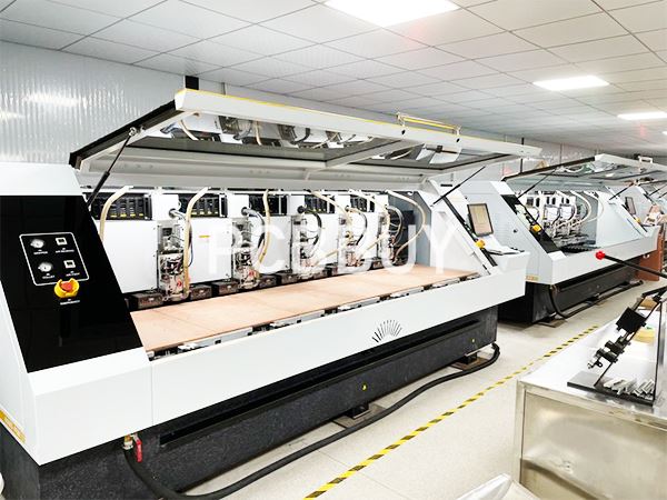
PCBBUY focuses on PCB applications in automotive electronics, industrial control, power and electrical systems, power supplies, energy storage, new energy, and embodied robotics. These applications may require multilayer structures, high-density interconnections, controlled impedance, and specialized drilling processes.
PCBBUY’s relevant PCB manufacturing capabilities include:
-
Large-size PCB production: Maximum production size of 1000 × 600 mm
-
HDI technology: Support for first-order and second-order HDI structures
-
Laser-drilled blind vias: Minimum diameter of Φ0.075 mm
-
Mechanically drilled blind vias: Minimum diameter of Φ0.15 mm
-
Controlled-depth drilling: Accuracy of ±15 μm for applicable step-hole and slot processes
-
High-frequency and high-speed materials: Support for materials from Rogers, TUC, Isola, and other manufacturers
-
Mixed-material lamination: Support for asymmetric and heterogeneous mixed-material lamination
-
Inspection and testing: AOI, flying-probe testing, and four-wire low-resistance testing
It is important to distinguish between controlled-depth drilling for step holes or slots and back drilling for via-stub removal. Although both processes require depth control, the published ±15 μm capability for applicable step-hole and slot processes should not automatically be interpreted as a guaranteed back-drill depth tolerance.
For projects requiring back drilling, PCBBUY’s engineering team should review the complete design package and confirm the achievable back-drill depth tolerance, residual stub specification, drilling diameter, and inspection method before production.
Back Drill Design Recommendations for High-Speed PCBs
To improve manufacturing feasibility and avoid unnecessary production risks, designers should follow several practical guidelines:
-
Specify the back-drill entry side clearly.
The top and bottom sides may require different drilling depths. -
Identify the “do-not-cut” layer.
A layer-based reference is often more practical than using only a nominal depth. -
Define the maximum residual stub length.
The requirement should be based on signal-integrity simulation and channel performance. -
Allow sufficient clearance for the larger drill.
The back-drill opening—not the original via diameter—must be used when checking nearby copper features. -
Avoid back drilling every via unnecessarily.
Apply the process to signal-critical vias when justified by the electrical design. This can help control manufacturing complexity and cost. -
Confirm the manufacturer’s actual process capability.
Do not assume that a general tolerance or a tolerance for another controlled-depth process applies to your specific back-drilling project.

Conclusion
Back drill depth tolerance in high-speed PCBs defines how accurately a manufacturer can remove unwanted via stubs without damaging functional PCB structures. If the drilling depth is insufficient, excessive stub length may remain. If the drilling depth is excessive, important pads, planes, or dielectric structures may be affected.
For reliable results, back-drill depth tolerance should be evaluated together with the final PCB stackup, layer registration, drill diameter, residual stub length, and copper clearances. Designers should clearly identify the drilling side and stop layer and confirm the manufacturer’s verified process capability before production.
For complex applications such as automotive electronics, industrial control, power systems, energy storage, and embodied robotics, early engineering review can help determine whether back drilling is necessary and what tolerance is appropriate for the specific high-speed design.
FAQ
1. What is back drill depth tolerance in high-speed PCBs?
Back drill depth tolerance is the permitted variation between the specified back-drilling depth and the actual depth achieved during PCB manufacturing.
2. Why is back drill depth tolerance important?
It ensures that the manufacturer can remove the required portion of a via stub without drilling into functional pads, copper planes, or signal layers.
3. What happens if the back drill is too shallow?
A longer residual via stub may remain, potentially increasing signal reflections, resonance, and impedance discontinuities in high-speed signal channels.
4. What happens if the back drill is too deep?
Excessive drilling may damage functional copper structures, reduce dielectric thickness, or interrupt electrical connections that must remain intact.
5. Is there a universal back drill depth tolerance for all high-speed PCBs?
No. The appropriate tolerance depends on the PCB stackup, material thickness variation, drilling equipment, registration accuracy, residual stub requirements, and the manufacturer’s process capability.
6. Should I specify drilling depth or the stop layer?
Whenever possible, specify the back-drill entry side and the layer that must not be cut. The manufacturer can then determine the actual drilling depth according to the final manufactured stackup.
7. Is PCBBUY’s ±15 μm controlled-depth drilling accuracy applicable to back drilling?
The ±15 μm figure refers to applicable controlled-depth drilling for step-hole and slot processes. It should not automatically be treated as a guaranteed back-drill depth tolerance. Specific back-drilling capability must be confirmed through engineering review.
8. What information should be included in a back-drilling data package?
The package should include the back-drill table, entry side, stop layer, back-drill diameter, maximum residual stub length, clearance requirements, stackup, and any inspection or verification requirements.
Industry Category








