Decoupling Capacitor Placement PCB
By:PCBBUY 08/12/2021 17:03

Do you know what is decoupling capacitor in PCB? In this article, we will provide you everything about decoupling capacitor in PCB, please check the content we prepare below to learn more information.
What is decoupling capacitor?
In the strictest sense, there isn’t a specific component that’s defined as a decoupling capacitor. Rather, the term decoupling capacitor refers to the function of a capacitor in an electronic circuit. A decoupling capacitor is one that stabilizes the voltage on the power supply plane.
In any design that involves semiconductor ICs, you’ll always need decoupling capacitors. That’s because the voltage supplied to the components is far from ideal. Unlike the perfect horizontal line depicted in theory, voltage readings in real-life applications tend to fluctuate even if you’ve got the cleanest power supply.
The decoupling function as reservoir and it acts in two ways to stabilize the voltage. When the voltage increases above the rated value, the decoupling capacitor absorbs the excessive charges. Meanwhile, the decoupling capacitor releases the charges when the voltage drops to ensure the supply is stable.
Often, you’ll need at least two coupling capacitors of different values to stabilize the voltage supplied to a component’s VDD pin. A capacitor in the range of 10 uF acts as a larger buffer to smoothen low-frequency fluctuations. High-frequency changing in voltage is dealt with a smaller capacitor, typically around 100 nF.

Why decoupling capacitor placement in PCB matters?
Ever wonder what would happen if you skipped decoupling capacitors in your design? I’ve done that for curiosity and here are a few signs to look out for.
An onboard microcontroller will have trouble operating as the voltage fluctuation can send it into brownout mode where it gets reset. Any attempts to get reliable ADC conversion will be futile, as the analog voltage supply is anything but stable. If you’re to send a PCB board that has no decoupling capacitors installed to the field, you’ll have weirder problems due to the greater electrical noises.
So, does placing a few decoupling capacitors on the PCB solve the problems? It depends.
The placement of decoupling capacitors is crucial to mitigating voltage fluctuations. If you’re not placing the capacitors at the right place, the effect will be minimal at best. In some cases, the wrong placement of decoupling capacitors can be a problem by itself, as it could pick up EMI coupled onto the copper trace.
Where to place decoupling capacitor placement in PCB?
Unlike finding the best spot for a modern vase, placing decoupling capacitors is easier.
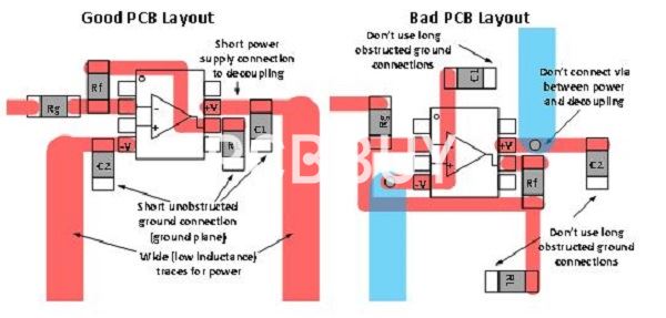
The golden rule of decoupling capacitor placement is to minimize the distance between the component’s voltage pin and the capacitor. This means you’ll need to place the decoupling capacitor as close as possible to the IC’s pin. If you’re designing a multilayer PCB, place the capacitor beneath the component’s pad. On a single-layer design, the capacitor is placed near to the pin and routed with a short trace.
As mentioned, you’ll need a 10uF and a 100 nF capacitor to stabilize against low and high-frequency fluctuations. The 100 nF capacitor should be placed closest to the voltage pin followed by the 10 uF capacitor. Repeat the process for as many VDD pin on the IC. There are some cases where the lack of space prevents the 1 decoupling capacitor per pin principle. In such instances, you’ll still need a minimum of 1 decoupling capacitor per component.
· Place the capacitor near the signal source: Decoupling capacitors should be placed as close as possible to the source for decoupling the signal. This means the caps should be placed on the pin for ICs and near the connector for I/O signals.
· Connect capacitor in series for I/O signal traces: To remove low-frequency transients from input and output signals, the capacitor should be connected in series with the trace. High-frequency will pass through the capacitor, but low-frequency and DC will be blocked. Additionally, small caps should be used for high-frequency transients and large caps for low-frequency transients.
· Put the capacitor in parallel for power pins and grounds: Decoupling the I/O signal paths and power distribution and grounding is not that important, but the elimination of AC or coupling of DC is critical. Therefore, the capacitor should be connected in parallel with the signal path.
· To minimize high-frequency EMI, connect a capacitor in parallel with a resistor: Decoupling capacitors can also be connected in parallel with resistors to filter out unwanted HF while allowing LF and DC to flow through.
· Connect the capacitor before the ground plane connection: Connect the capacitor to the component pin before connecting it to the via to reach the power plane. This ensures smooth current flow through the plane.
· Place the capacitor on the same layer as the digital and analog ground pours: Decoupling capacitors can also be used to separate analog and digital signals. This is accomplished by connecting a capacitor between AC and digital PCB ground pours.
Industry Category


