Electronic components used in PCB
By:PCBBUY 08/11/2021 17:02

Over the last few decades’ electronics technologies and product development have been growing and rapidly have become more and more complex. Knowledge of electronic components is essential to build successful electronic products. In this passage, we are going to provide all the knowledge about electronic components in PCB. Check and read the content below.
What is the introduction of electronic components in PCB?
While Electronic components process information in form of electrical signals, a Printed Circuit Board PCB is the skeletal structure on which the electronic components are mounted and soldered to hold them together and provide pathways for information to flow between components through PCB traces.
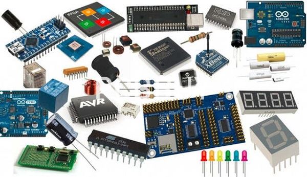
Some of the most commonly used electronic components are resistors, capacitors, inductors, diodes, LEDs, transistors, Crystals & Oscillators, Electromechanical components like relays & Switches, ICs, and connectors. These components have leads/terminals and are available in specific standardized packages that the designer can choose to suit his application. SMT (Surface Mount Technology) and Through-hole are the two types of mounting techniques used to place components on a PCB.
What are the common components in PCB?
Resistors – Control Energy
Resistors are the foundations of current control—which is why they’re so often used in PCBs. These two-ended electrical pieces are fairly simple to understand and integrate into different projects. Resistance is often defined as the “ease” with which objects allow electricity to flow through them. Think of the difference between insulators and conductors; the former obviously possesses higher resistance than the latter.
Resistors, on the other hand, allow users to precisely define an object’s level of resistance. They are designed to resist the flow of an electric current by converting the electrical energy into heat—heat that is then dissipated. Resistors can be made of a wide range of materials and come in many different styles. The most common (and highly recommended for beginners) would be resistors made of carbon film in the axial style. Axial style resistors have leads on both ends of the rod. Their body is marked with different colored rings that represent the resistor’s resistance value.
Capacitors – Store Energy
Outnumbered only by resistors, capacitors are electronic components you’ll definitely find on every PCB board. Whereas resistors control an electric charge, capacitors temporarily store it. Think of them as tiny batteries with even tinier storage space. They are capable of losing and gaining full charge in a split second. Because of this, capacitors are commonly used for “filtering:” a process where a backup source of energy takes over when the main source of power drops in order to not lose or reset data.
In PCBs, capacitors electrostatically store energy to later release it to wherever power is needed in the circuit. It works by collecting opposing charges (positive and negative) on two conductive plates (typically metal) with some form of insulating material between them.
There are different types of capacitors, often categorized by the conductive material of the plates or the insulating material that separates them. Most beginners and casual hobbyists use polyester capacitors, ceramic capacitors, or radial capacitors. You’ll notice that some capacitors resemble resistors. The most telling difference is that resistors have leads on opposite ends. Capacitors have two leads protruding from the same side.

Transformers – Transfer Energy
General transformers transfer power from one source to another through a process called “induction.” PCB transformers function the same way. They transfer electrical energy from different circuits—and convert them—by increasing or decreasing the voltage. As with resistors, they technically regulate current. The biggest difference is that they provide more electrical isolation than controlled resistance by “transforming” the voltage.
PCB transformers consist of two or more separate inductive circuits (called windings) and a soft iron core. The primary winding is for the source circuit—or where the energy will come from—and the secondary winding is for the receiving circuit—where the energy is going to. Transformers break down large amounts of voltage into smaller, more manageable currents so as not to overload or overwork the equipment.
Transistors – Amplify Energy
Resistors may be fundamental to current control but transistors are fundamental to all modern electronics. They can, in fact, be considered the building blocks.
Contrary to storing, regulating, or controlling charges on the PCB, transistors amplify them. A bipolar transistor, which is the most common type of transistor, has three areas and three pins in which the current flows and is amplified. There are two types of bipolar transistors; NPN and PNP. Both are composed of the (1) base, (2) collector, and (3) emitter, and have both P-type areas and N-type areas.
NPN transistors are more commonly used than PNP transistors for a number of reasons. However, both have their advantages and disadvantages depending on the project.
Diodes – Redirect Energy
Going back to our PCB board – city comparison, diodes are basically the one-way streets on a printed circuit board. These two-terminal components control and redirect energy flow by allowing the current to flow down one direction and blocking it from moving down the other. The flow is typically from the positive terminal (called the anode) to the negative terminal (called the cathode).
Like resistors, diodes use electrical resistance to control the flow of energy. High resistance in one direction and zero resistance in the other effectively blocks the current from flowing in the wrong direction and potentially damaging the equipment.
The most common diode that many people—even non-hobbyists—are familiar with is light-emitting diodes or LEDs. Other common examples of PCB diodes include Zener, high-speed switching diodes, and Schottky diodes.
Battery – Provide Energy
In theory, everyone knows what a battery is. Perhaps the most widely-purchased component on this list, batteries are used by more than just electronic engineers and hobbyists. People use this little device to power their everyday objects; remotes, flashlights, toys, chargers, and more.

On a PCB, a battery basically stores chemical energy and converts it into usable electronic energy to power the different circuits present on the board. They use an external circuit to allow electrons to flow from one electrode to the other. This forms a functional (but limited) electric current.
The current is limited by the conversion process of chemical energy to electrical energy. For some batteries, this process could finish in a matter of days. Others might take months or years before the chemical energy is completely spent. This is why some batteries (like the batteries in remotes or controllers) need to be changed every few months whereas others (like wrist watch batteries) take years before they’re all used up.
There are different types of batteries available for PCBs, but we would definitely recommend getting rechargeable ones.
Integrated Circuits – Multi-Function Powerhouses
Integrated circuits are the powerhouses of all PCBs. Batteries might be the source of energy, but circuits are the power factories. These tiny wafers house thousands (or even millions) of transistors, resistors, and capacitors. Because of that, they can amplify, oscillate, and process energy in a printed circuit board—just to name a few functions.
As the name suggests, integrated circuits (or ICs) are basically circuits that have been integrated into a PCB board through minimization. These wafer-like components are usually made of silicone and encased in a plastic housing. The more modern ones can also use digital or analog technology to perform calculations.
These types of technology further define the two types of ICs: digital and analog. The best one for beginners depends on the kind of project to be carried out. Digital Integrated Circuits are typically used in computers and consumer electronics. Analog Integrated Circuits (also called Linear) are typically used in audio and radio frequency amplification.
Industry Category


