
How Do You Choose Low Dk Materials for Millimeter Wave PCB Design?
By:PCBBUY 08/25/2026 15:46
Introduction
When PCB operating frequencies move into the millimeter-wave range, material selection becomes much more than a question of choosing a "high-frequency laminate."
At these frequencies, the dielectric properties of the PCB material directly influence electromagnetic propagation, impedance, phase delay, loss, and the behavior of transmission lines and antennas.
This is why engineers designing radar modules, high-frequency sensors, wireless communication equipment, industrial sensing systems, and robotic perception electronics increasingly consider low Dk materials for millimeter wave PCB applications.
However, selecting a low-Dk laminate is not as simple as choosing the material with the lowest dielectric constant listed on a datasheet. From a PCB engineering perspective, a successful millimeter-wave design requires the material, stackup, copper structure, transmission-line geometry, vias, fabrication tolerances, and measurement requirements to work together.
A material with a favorable nominal Dk can still produce disappointing results if the actual stackup, dielectric thickness, copper geometry, registration, or manufacturing variation is not properly controlled.
For this reason, experienced PCB engineers normally evaluate Dk, Df, frequency dependence, material consistency, dielectric thickness, copper surface characteristics, impedance requirements, and manufacturability as one system.
For automotive electronics, industrial control, new-energy equipment, power electronics, energy-storage systems, and embodied robotics, this engineering approach is particularly valuable because high-frequency circuits often operate alongside power circuits, mechanical constraints, thermal stress, and long-term reliability requirements.
What Does Dk Mean in a Millimeter-Wave PCB?
Dk, or dielectric constant, describes how a dielectric material affects the propagation of an electromagnetic field compared with a vacuum.
In practical PCB design, Dk influences several important characteristics:
Signal propagation velocity
Transmission-line impedance
Electrical wavelength
Phase delay
Antenna dimensions
Coupling between conductors
Stackup geometry
A microstrip, stripline, coplanar waveguide, or other transmission structure interacts with both the dielectric material and the surrounding air or adjacent materials.
Therefore, effective Dk matters in actual PCB design.
Why Are Low Dk Materials Important at Millimeter-Wave Frequencies?
Lower dielectric constant materials can provide useful electrical characteristics for certain high-frequency structures.
A lower Dk can increase propagation velocity and, depending on the transmission-line configuration, can allow a designer to achieve a desired impedance with different trace geometries.
For millimeter-wave circuits, this can affect:
Phase matching
Transmission-line dimensions
Antenna size
Coupling behavior
Delay
RF performance
The correct material depends on the entire RF structure. For example, an antenna designer may prioritize one set of dielectric characteristics, while a long transmission line may have a different optimization target. Therefore, material selection should begin with the electromagnetic requirements of the actual circuit, rather than simply selecting the lowest Dk material available.
Is Low Dk the Same as Low Loss?
No.
This distinction is essential when choosing low Dk materials for millimeter wave PCB applications.
Two important dielectric parameters are:
Dk — Dielectric Constant
Dk primarily affects electromagnetic propagation and impedance behavior.
Df — Dissipation Factor
Df describes dielectric loss.
A material can have a relatively low Dk but still not be the optimum choice for a low-loss millimeter-wave transmission line if its dielectric loss is not suitable for the application.
Therefore, a practical material-selection process should consider:
Dk + Df + frequency + stackup + copper structure + transmission-line geometry
rather than Dk alone.

Why Does Frequency Matter When Selecting PCB Materials?
The dielectric properties of a laminate are not necessarily constant over the entire frequency range.
A material may exhibit different measured dielectric characteristics depending on:
Measurement method
Frequency
Temperature
Resin content
Glass weave
Material construction
This becomes particularly important as PCB applications move toward millimeter-wave frequencies.
For example, a material specification measured under one test condition should not automatically be treated as the exact effective Dk of a finished 77 GHz transmission line.
For a demanding design, the material datasheet, stackup construction, and intended operating frequency should therefore be considered together.
What Are Common Millimeter-Wave PCB Applications?
Millimeter-wave technology is increasingly relevant to several of the industries served by Lieban.
Automotive Radar
Automotive radar systems are one of the most recognizable millimeter-wave PCB applications.
Radar modules need controlled electromagnetic propagation and stable RF characteristics
while operating in an environment with:
Temperature variation
Vibration
Electromagnetic interference
Tight mechanical constraints
Material consistency and PCB manufacturing accuracy therefore matter alongside RF design.
Industrial Sensing
Industrial equipment may use high-frequency sensing for:
Distance measurement
Motion detection
Object detection
Process monitoring
The PCB must combine RF performance with industrial reliability.
Embodied Robotics
Robotic systems increasingly combine:
Radar
High-frequency sensors
Wireless communication
Cameras
Processors
Motor-control electronics
A compact high-density PCB may therefore need to accommodate both RF transmission lines and conventional digital or power circuits.
New Energy and Power Electronics
Millimeter-wave circuits are not necessarily part of the power stage itself, but high-frequency communication, sensing, and control electronics may coexist with power-conversion circuitry.
This makes stackup planning particularly important because sensitive RF structures need appropriate reference planes and sufficient isolation from noisy power circuits.

What Materials Can Be Used for Millimeter-Wave PCBs?
Material selection depends on the application. For conventional digital and lower-frequency electronics, standard FR-4 materials can be suitable.
For demanding high-frequency and millimeter-wave circuits, specialized high-frequency laminates are often considered because their dielectric and loss characteristics are more suitable for RF applications.
The Lieban manufacturing capability file lists:
FR-4 materials from Kingboard and Shengyi
Halogen-free FR-4 materials
High-frequency materials including Rogers series and Taier series
Rogers 3000–4000 series material documentation
Importantly, the available manufacturing list does not mean that every material in these series has the same Dk or Df characteristics. The exact material grade should therefore be selected according to the customer's RF design requirements and confirmed against the relevant material datasheet before production.
How Should You Compare Low Dk Materials for Millimeter-Wave PCB?
A practical comparison should include more than the nominal dielectric constant.
Material Selection Factor | Why It Matters at Millimeter-Wave Frequencies | Engineering Recommendation |
Dk | Affects propagation, impedance and phase | Confirm the Dk at the relevant frequency and test method |
Df | Influences dielectric loss | Evaluate together with insertion-loss requirements |
Frequency stability | RF properties may vary with frequency | Use material data relevant to the intended operating band |
Dielectric thickness | Directly affects impedance and field distribution | Define the stackup before final trace geometry |
Resin/glass construction | Can affect local effective Dk | Consider glass-weave effects for sensitive RF traces |
Copper structure | Influences conductor loss and impedance | Specify copper thickness and fabrication requirements |
Thermal behavior | Material properties can shift with temperature | Important for automotive and industrial applications |
Manufacturing tolerance | Changes actual RF geometry | Match the material selection with PCB process capability |
This is why a millimeter-wave PCB should be treated as an electromagnetic structure, not simply as a conventional multilayer board using a more expensive laminate.
Why Does Glass Weave Matter for Millimeter-Wave PCB Design?
This is one of the more advanced issues that is sometimes ignored in general PCB articles.
A PCB dielectric is not always electromagnetically uniform.
The laminate contains resin and glass reinforcement, and these components can have different dielectric characteristics. At lower frequencies, the resulting variation may be relatively manageable.
At millimeter-wave frequencies, however, the electromagnetic wavelength becomes much shorter, making local dielectric variation more relevant.
For sensitive RF traces, engineers may therefore need to consider:
Trace orientation
Glass-weave interaction
Trace-to-glass relationship
Differential-pair skew
Effective Dk variation
The exact strategy depends on the material construction and RF architecture. This is another reason why simply choosing a low nominal Dk material does not automatically guarantee the best millimeter-wave performance.
How Does Stackup Design Affect Low Dk Millimeter-Wave PCBs?
The material and stackup cannot be separated.
A PCB stackup determines:
Dielectric thickness
Reference-plane position
Transmission-line geometry
Coupling
Impedance
Via transition length
For example, a millimeter-wave microstrip may be highly sensitive to the distance between the signal layer and its reference plane. If the dielectric thickness changes, the trace width required to achieve a target impedance may also change.
Therefore, the correct workflow is:
Material selection → Stackup → Field structure → Transmission-line geometry → Impedance verification → Fabrication
rather than:
Choose material → copy a trace width → manufacture

How Does Lieban Handle High-Frequency Stackup Requirements?
Lieban's published manufacturing capability supports 1–26 layer PCBs, with conventional multilayer stackups from 4 through 12 layers and 14–26 layers referenced according to customer process requirements. The manufacturing list also identifies Rogers and Taier high-frequency materials as available material options. For a millimeter-wave project, the recommended approach is to provide the engineering team with:
Target operating frequency
Required impedance
Material grade
Layer stackup
Copper thickness
Trace width
Trace spacing
RF structure
Via requirements
Relevant electrical test requirements
The stackup should then be evaluated as a complete structure.
This is particularly important when the PCB combines RF circuits with conventional digital, control, or power sections.
Why Is Controlled Impedance Critical for Millimeter-Wave PCBs?
At millimeter-wave frequencies, even relatively small changes in transmission-line geometry can affect electrical performance. Controlled impedance therefore becomes an important manufacturing requirement.
Lieban's published general process capability specifies a minimum impedance tolerance of ±10%. For example, a nominal 50 Ω impedance would correspond to a production range of 45–55 Ω under that stated tolerance.
However, engineers should not interpret this as automatically sufficient for every millimeter-wave application. If a customer requires tighter RF impedance control, the requirement should be explicitly specified and technically reviewed.
This is particularly important for:
Radar RF lines
Antenna feeds
High-frequency filters
RF transceiver paths
Sensitive microwave interconnects
The actual acceptable impedance tolerance should be determined by the electrical design.
Why Do PCB Line Width and Registration Matter at Millimeter-Wave Frequencies?
At high frequencies, the physical dimensions of the transmission line become part of the electrical design.
A small variation in:
Trace width
Trace spacing
Dielectric thickness
Copper thickness
Layer registration
can change the actual electromagnetic behavior.
PCBBUY's published process capability includes 2/2 mil minimum line/space capability for HDI, while conventional outer-layer design capability varies with copper thickness. The published process data also lists ±2 mil minimum external layer image-to-hole positioning and ±2 mil layer-to-hole positioning accuracy.
These capabilities are particularly useful when a high-density RF layout has to coexist with fine-pitch components and compact routing. The exact line width and spacing must still be determined from the selected material, stackup, copper thickness, impedance target, and fabrication method.
Can HDI Be Used for Millimeter-Wave PCB Designs?
Yes, when the design requires high routing density or short interconnect transitions.
Lieban's published HDI capability includes:
First-order HDI: 4–16 layers
Second-order HDI: 6–10 layers
Minimum HDI hole diameter: 0.10 mm
Laser blind vias down to 0.075 mm
Minimum HDI line/space of 2/2 mil
Minimum single-side annular ring of 3 mil
Laser via filling by copper plating
The published process information specifies laser via filling depths of 0.05–0.15 mm with a ±15% tolerance for that process. For millimeter-wave applications, HDI should not be adopted simply because it is technologically advanced.
Instead, it should be considered when it provides a clear advantage in:
Component density
Routing
Via transition length
Board size
RF layout architecture
How Does Copper Thickness Affect Millimeter-Wave PCB Performance?
Copper thickness is normally selected based on both electrical and manufacturing requirements. For millimeter-wave transmission lines, conductor geometry influences impedance and conductor loss.
A thicker copper layer is not automatically better for RF performance. For example, power electronics may require heavy copper for current carrying capacity, while an RF transmission line may require a different copper geometry.
PCBBUY's general process capability supports conventional outer-layer finished copper from 1 oz to 4 oz, with customized copper thickness available up to 15 oz; inner-layer finished copper is listed from H oz to 3 oz, with customization available up to 8 oz.
For an RF board that also contains high-current sections, copper thickness should therefore be planned by layer rather than simply applying the same copper thickness throughout the entire stackup.
Why Should You Consider Copper Surface Effects at Millimeter-Wave Frequencies?
As frequency increases, current distribution becomes increasingly concentrated near the conductor surface.
This is related to the skin effect.
Consequently, conductor loss becomes an important part of the overall insertion-loss budget.
The actual loss depends on factors such as:
Frequency
Copper conductivity
Copper thickness
Surface profile
Trace geometry
Current distribution
For this reason, material selection should not focus exclusively on dielectric Dk and Df.
A low-loss dielectric paired with an unsuitable conductor structure may still produce unsatisfactory RF performance.
When a customer's design has strict insertion-loss requirements, the copper construction and fabrication method should therefore be reviewed together with the laminate selection.
Why Is Material Consistency Important for Millimeter-Wave PCBs?
For a prototype, a small variation may not immediately cause a visible functional failure.
For production, however, repeatability becomes much more important.
If dielectric thickness, material construction, trace geometry, or layer registration varies from board to board, the electrical characteristics may also shift.
This matters particularly for:
Radar
RF transceivers
Antenna arrays
High-frequency sensors
Precision measurement equipment
For this reason, a reliable millimeter-wave PCB manufacturer should be able to translate the customer's specified material and stackup into a controlled manufacturing process.
How Does Lieban Support Production Quality for High-Frequency PCBs?
The manufacturing capability file provides several process controls relevant to high-frequency multilayer PCB production.
For example:
Hole-position tolerance: ±0.05 mm
PTH hole diameter tolerance: ±0.075 mm, with ±0.05 mm available by specification
Minimum conventional drilled hole: 0.15 mm
Minimum HDI hole: 0.10 mm
Conventional through-hole aspect ratio: 10:1, with customization up to 20:1
Standard through-hole copper thickness: average ≥18 μm
External layer image-to-hole positioning: ±2 mil
These are manufacturing controls rather than direct "millimeter-wave performance guarantees." Their importance is that RF performance depends on the physical geometry actually produced.
What Inspection Should Be Considered for Millimeter-Wave PCBs?
A high-frequency PCB should be evaluated using an inspection plan appropriate to the design.
Depending on customer requirements, this can include:
Electrical testing
Flying-probe testing
Four-wire low-resistance testing for applicable products
Impedance testing
Impedance coupons
Thermal-shock reliability testing
Solderability testing
Dimensional inspection
PCBBUY's published capability lists flying-probe testing, with four-wire low-resistance testing available for automotive, medical, and military applications. It also identifies impedance reports and impedance coupons as applicable shipment documentation/verification items depending on the product requirements.
For a millimeter-wave PCB, the specific inspection and acceptance criteria should be defined in the engineering specification rather than assuming that a standard electrical continuity test is sufficient to validate RF performance.
What Should You Ask a PCB Manufacturer Before Ordering Low Dk Material?
A professional RF PCB inquiry should provide more information than simply saying:
"Please use a low Dk material."
A better specification includes:
Operating frequency
Target impedance
Material family
Exact material grade
Dk requirement
Df requirement
Measurement frequency/method where relevant
Finished dielectric thickness
Copper thickness
Trace width and spacing
Layer stackup
RF test requirements
Environmental requirements
This information allows the manufacturer to determine whether the proposed material and fabrication process are compatible with the design.
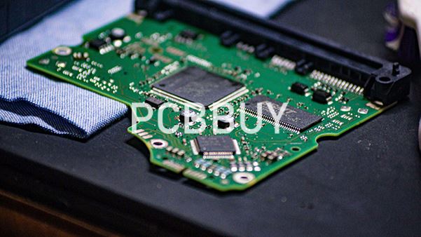
How Should Low Dk Materials Be Selected for Different Applications?
Automotive Radar
For automotive radar, material selection should prioritize stable RF behavior at the target frequency together with environmental reliability.
The PCB structure may need to balance:
Low dielectric loss
Controlled Dk
Stable impedance
Thermal performance
Mechanical reliability
Compact dimensions
For radar boards, the exact laminate grade should be selected based on the radar frequency and RF architecture rather than choosing a generic "high-frequency PCB."
Industrial Control and Sensing
Industrial systems may use high-frequency sensors or communication modules while also containing conventional control electronics. A hybrid stackup can sometimes be more practical than building the entire board from an expensive RF laminate.
The RF section can be designed around the required high-frequency material and stackup, while other sections can be optimized for cost, thermal performance, and manufacturing efficiency. The feasibility of such a mixed-material construction should be evaluated during stackup engineering.
Power and Energy Storage
In power and energy-storage systems, RF circuits may coexist with:
High-current copper
Switching power stages
Sensors
Communication interfaces
In this situation, low Dk material selection is only one part of the design.
Signal isolation, reference-plane planning, return-current paths, and power-noise management are equally important.
Embodied Robotics
Robotic systems are particularly interesting because they combine RF sensing with compact electronics.
A single system may contain:
Millimeter-wave radar
Wireless communication
High-speed digital processing
Motor drivers
Power conversion
Sensor interfaces
HDI technology and carefully planned multilayer stackups can help integrate these different electrical functions into a compact PCB.
PCBBUY ombination of multilayer production, high-frequency material options, HDI, fine-line capability, and controlled-impedance manufacturing can be evaluated for such mixed-technology designs.
How Can PCBBUY Help With Low Dk Millimeter-Wave PCB Manufacturing?
For customers developing RF and millimeter-wave electronics, Lieban's manufacturing capability provides several relevant building blocks. The documented capability includes high-frequency PCB materials from Rogers and Taier, including Rogers 3000–4000 series documentation; multilayer production from 1–26 layers; controlled impedance with a listed minimum tolerance of ±10%; HDI structures; laser blind vias; and fine-line fabrication.
For high-density HDI designs, the published capability includes 2/2 mil line/space, 0.10 mm minimum HDI hole diameter, and laser blind vias down to 0.075 mm, subject to engineering review for specific requirements.
For a millimeter-wave project, however, the most important point is not simply having access to high-frequency laminates.
The engineering team should confirm:
material grade → stackup → Dk/Df data → impedance → copper structure → via structure → manufacturing tolerances → inspection requirements
as one complete production plan.
Conclusion
Choosing low Dk materials for millimeter wave PCB applications requires considerably more engineering judgment than selecting the material with the lowest dielectric constant.
Dk affects electromagnetic propagation, impedance, phase, and transmission-line geometry, while Df and conductor characteristics influence signal loss. At millimeter-wave frequencies, frequency dependence, dielectric construction, glass-weave effects, copper geometry, stackup thickness, via structures, and manufacturing tolerances can all become important.
For this reason, the recommended engineering approach is:
Application requirements → Frequency → Material → Stackup → Transmission-line design → Manufacturing review → Verification
PCBBUY documented manufacturing capabilities provide a foundation for these demanding designs, including Rogers and Taier high-frequency material options, 1–26 layer PCB manufacturing, controlled-impedance processing, HDI, laser blind vias, fine-line fabrication, and customized copper thickness.
The published process capability also includes 2/2 mil HDI line/space, 0.10 mm minimum HDI hole diameter, 0.075 mm minimum laser blind-via diameter, ±2 mil external image-to-hole positioning, and conventional hole-position controls, providing the manufacturing precision needed for many high-density RF structures.
For automotive radar, industrial sensing, new-energy equipment, high-frequency control electronics, and embodied robotics, the most reliable approach is to involve the PCB manufacturer during the material and stackup selection stage, not after the RF layout has already been completed.
And one point is especially important: a low-Dk material is not automatically the best millimeter-wave material. The right choice is the material and PCB construction that can deliver the required RF performance while remaining stable, manufacturable, testable, and reliable in production.
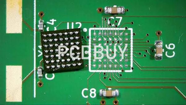
FAQ: Low Dk Materials for Millimeter Wave PCB
What are low Dk materials for millimeter-wave PCBs?
Low Dk materials are PCB dielectric materials with relatively low dielectric constants compared with conventional PCB materials. They can be useful for controlling propagation, impedance, phase, and transmission-line geometry in high-frequency and millimeter-wave circuits.
Is lower Dk always better for a millimeter-wave PCB?
No. Dk is only one material parameter. The appropriate material must also meet the required Df, frequency stability, thermal characteristics, dielectric thickness, mechanical requirements, and manufacturing constraints.
What is the difference between Dk and Df?
Dk describes the dielectric constant and strongly influences electromagnetic propagation and impedance. Df, or dissipation factor, describes dielectric loss. Both should be evaluated when selecting materials for millimeter-wave PCB applications.
Can standard FR-4 be used for millimeter-wave PCBs?
It depends on the application and required RF performance. Standard FR-4 may be unsuitable for demanding low-loss millimeter-wave transmission paths, but it can still be appropriate for other sections of a mixed-technology PCB. Material selection should be based on the actual electrical requirements.
Does Lieban provide high-frequency PCB materials?
Yes. The supplied manufacturing capability lists Rogers series and Taier series high-frequency materials, including Rogers 3000–4000 series documentation. The exact material grade should be confirmed according to the customer's design and the corresponding material datasheet.
Does Lieban provide specific low Dk values for Rogers materials?
The supplied manufacturing file identifies the available high-frequency material families but does not provide a universal Dk value for all Rogers or Taier materials. Therefore, the exact Dk and Df should be confirmed against the selected material grade rather than assumed.
Can Lieban manufacture controlled-impedance millimeter-wave PCBs?
Lieban's published capability specifies a minimum general impedance tolerance of ±10%. Tighter requirements should be explicitly specified and technically reviewed for the particular project.
Can HDI be used with high-frequency PCB materials?
Yes. Lieban's published HDI capability includes 1–3 stage HDI, laser drilling, fine-line processing, blind vias, and laser via filling. The specific material/HDI combination should be reviewed according to the stackup and manufacturing requirements.
What is the minimum HDI hole size supported by Lieban?
The published process capability lists a 0.10 mm minimum HDI hole diameter, while laser blind vias can be as small as 0.075 mm, subject to engineering review.
What is Lieban's minimum HDI line width and spacing?
The published HDI capability lists 2/2 mil minimum line width and spacing.
Can millimeter-wave PCBs combine RF and power circuits?
Yes, but the stackup and return-current paths need careful engineering. RF transmission lines should be appropriately referenced and isolated from high-noise switching or high-current structures.
Does copper thickness matter for millimeter-wave PCBs?
Yes. Copper thickness influences transmission-line geometry and conductor loss. It should therefore be selected together with the RF stackup and impedance requirement rather than independently.
What information should I provide when requesting a millimeter-wave PCB quote?
Provide the operating frequency, exact material grade if specified, Dk/Df requirements, stackup, target impedance, copper thickness, trace geometry, via structure, board thickness, and electrical/reliability testing requirements. This allows the PCB manufacturer to evaluate both RF performance and manufacturability.
Can Lieban provide impedance testing or reports?
The supplied process information lists impedance reports and impedance coupons where applicable, along with flying-probe testing and other inspection options. The exact verification plan should be defined according to the customer's product requirements.
Industry Category








