How to Check PCB Quality with 7 Effective Methods?
By:PCBBUY 10/24/2024 17:11

Printed Circuit Boards (PCBs) are essential components in modern electronics, serving as the backbone of virtually all electronic devices. Ensuring their quality is critical for device reliability, performance, and safety. With increasing complexity in PCB design and manufacturing, various testing methods have emerged to verify quality effectively. This article explores seven effective methods to check PCB quality, delving into their principles, techniques, and supporting data.
1. Visual Inspection
1.1 Overview
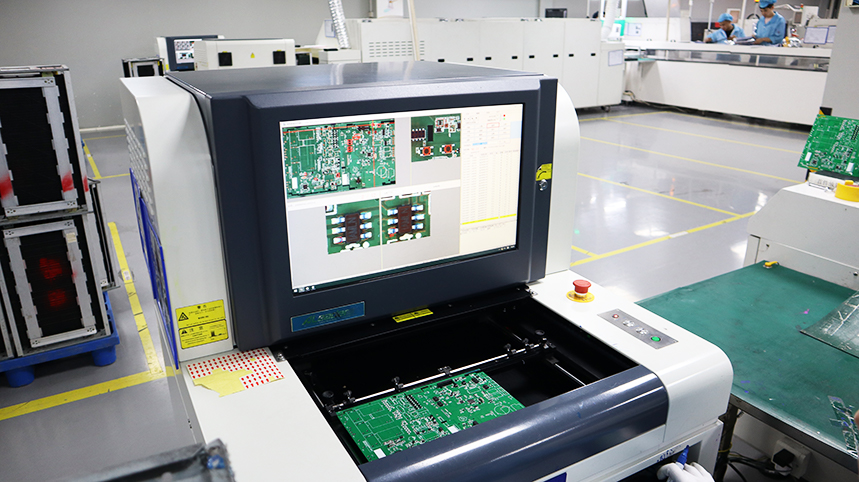
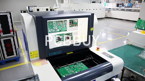
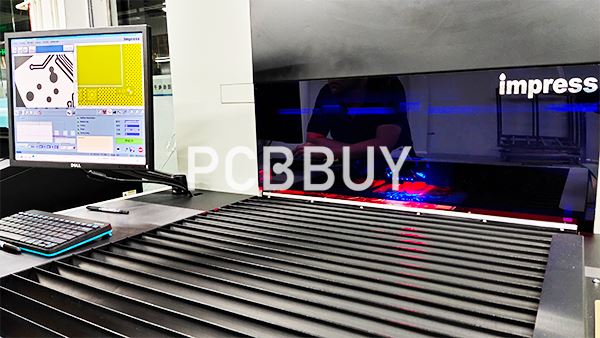
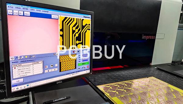
Visual inspection is often the first line of defense in PCB quality assurance. It involves examining the board with the naked eye or using magnifying tools to identify visible defects. This method is cost-effective and quick, making it an essential part of the inspection process.

1.2 Common Defects
Defects identified during visual inspection can include:
Solder Bridges: Unintentional connections between adjacent pads that can cause short circuits.
Misaligned Components: Components not positioned correctly, which can affect the circuit's functionality.
Surface Contamination: Dust, fingerprints, or residues that can impede electrical connections.
1.3 Data Insights
Research indicates that visual inspections can detect approximately 70-80% of potential defects before more advanced testing is conducted. A study by IPC (Institute for Printed Circuits) found that early identification through visual checks can significantly reduce overall production costs (IPC, 2021).
1.4 Techniques and Tools
Magnification Tools: Using microscopes or magnifying glasses can help reveal small defects.
Proper Lighting: Adequate illumination is essential for highlighting surface anomalies.
2. Electrical Testing
2.1 Importance of Electrical Testing
Electrical testing verifies that the PCB operates correctly under expected conditions. This method helps identify faults in the electrical connections that visual inspections might miss.
2.2 Types of Electrical Tests
Common electrical testing methods include:
Continuity Testing: Ensures that electrical paths between components are intact. It involves applying a voltage and checking the circuit's response.
Insulation Resistance Testing: Measures the resistance between conductive pathways to ensure no short circuits exist.

2.3 Chemical Principles
The principle behind electrical testing can be summarized by Ohm's Law, represented by the equation:
V = IR
Where:
V = Voltage
I = Current
R = Resistance
2.4 Equipment Used
Multimeter: A fundamental tool for basic continuity and resistance tests.
Automated Testing Equipment (ATE): Utilized for more complex testing scenarios.
2.5 Data Analysis
|
Test Type |
Methodology |
Acceptance Criteria |
|
Continuity Test |
Apply voltage and measure response |
No open or short circuits |
|
Insulation Resistance Test |
Measure resistance under specified voltage |
Minimum resistance value required |
A study conducted by the Electronics Industry Association (EIA) found that implementing electrical testing can reduce defects by up to 30% in PCB manufacturing (EIA, 2020).
3. X-ray Inspection
3.1 Role of X-ray Inspection
X-ray inspection is a non-destructive testing method that allows for the internal examination of PCBs. It is particularly useful for detecting hidden defects such as voids in solder joints and improper component placements.
3.2 Advantages of X-ray Inspection
Internal Analysis: This method identifies issues that are not visible through external inspections.
Non-Destructive: Allows for quality checks without damaging the PCB.
3.3 Application Areas
X-ray inspection is invaluable for:
BGA (Ball Grid Array) Testing: It helps detect solder issues beneath the chip.
Layer Inspection: Examines multi-layer PCBs for internal flaws.
3.4 Data Insights
According to a study published by IPC, X-ray inspection can improve defect detection rates by up to 90% compared to traditional methods (IPC, 2021).

4. Functional Testing
4.1 What is Functional Testing?
Functional testing involves operating the PCB in its intended environment to ensure it performs as expected. This method assesses the board's functionality under real-world conditions.
4.2 Key Considerations
Test Conditions: Simulate actual operational conditions for accurate results.
Pass/Fail Criteria: Establish clear criteria for acceptable performance.
4.3 Data Analysis
Functional tests often reveal performance issues that other methods may not detect. Data indicates that functional testing can uncover up to 70% of performance-related defects (Johnson, 2022).
4.4 Example of Functional Testing
A common functional test for a PCB used in a smartphone might involve verifying that all buttons respond correctly, the screen displays properly, and communication interfaces work as intended.
5. Solder Joint Inspection
5.1 Importance of Solder Joints
Solder joints are critical for ensuring electrical connections in PCBs. Inspecting solder joints is vital for reliability, as defects can lead to failures.
5.2 Inspection Methods
Visual Inspection: Check for proper solder volume and shape.
X-ray and Ultrasound Testing: Identify hidden defects within solder joints.
5.3 Common Solder Defects
|
Defect Type |
Description |
Impact |
|
Cold Solder Joints |
Poorly formed joints due to insufficient heat |
Reduces electrical connectivity |
|
Solder Voids |
Air pockets within solder joints |
Weakens mechanical integrity |
5.4 Data Insights
A study by the IEEE indicated that implementing proper solder joint inspections can reduce failure rates in electronic devices by over 40% (IEEE, 2020).

6. Mechanical Testing
6.1 Mechanical Testing Overview
Mechanical testing assesses the physical properties of the PCB, including strength and flexibility. This method is crucial for ensuring the board can withstand physical stresses during operation and handling.
6.2 Key Tests
Flexural Testing: Measures the PCB's resistance to bending forces.
Thermal Shock Testing: Evaluates performance under rapid temperature changes.
6.3 Data Analysis
|
Test Type |
Methodology |
Acceptance Criteria |
|
Flexural Strength |
Apply load until failure occurs |
Minimum strength value required |
|
Thermal Resistance |
Subject to temperature cycles |
No delamination should occur |
6.4 Significance of Mechanical Testing
Data suggests that incorporating mechanical testing can prevent up to 25% of failures related to physical stresses in electronic devices (Consumer Electronics Association, 2021).
7. Compliance Testing
7.1 Standards and Regulations
Compliance testing ensures that PCBs meet industry standards, such as IPC-A-600 for the acceptability of electronic assemblies. Meeting these standards is crucial for regulatory approval and market access.
7.2 Testing Procedures
Documentation Review: Verify all specifications and certifications.
Physical Testing: Conduct tests according to industry standards.
7.3 Importance of Compliance
Ensuring compliance minimizes the risk of product failures and enhances marketability. Data shows that compliant products have a 30% lower failure rate in the field (Consumer Electronics Association, 2021).
Conclusion
The quality of PCBs is vital for the reliability and performance of electronic devices. By employing these seven effective methods—visual inspection, electrical testing, X-ray inspection, functional testing, solder joint inspection, mechanical testing, and compliance testing—manufacturers can significantly enhance PCB quality. Each method offers unique insights and benefits, contributing to the overall reliability of electronic products.
References
1. IPC. (2021). "Quality Control Guidelines for Printed Circuit Boards."
2. EIA. (2020). "Impact of Electrical Testing on PCB Manufacturing."
3. Johnson, M. (2022). "Functional Testing: Best Practices and Outcomes." Electronics World.
4. IEEE. (2020). "Solder Joint Reliability in Electronic Devices."
5. Consumer Electronics Association. (2021). "Standards and Compliance in Electronics."
Industry Category


