How to Determine PCB Thickness during the PCB Layout Process?
By:PCBBUY 12/22/2021 09:39

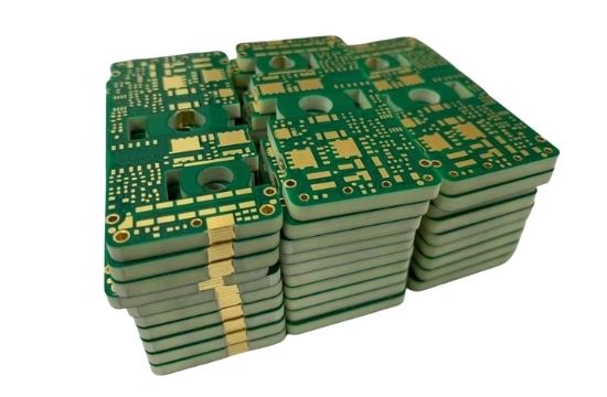
The board thickness is always based on both the insulating material and the top layer material; at the beginning of Circuit boards, this would be Bakelite sheet included as the top layer of the plywood at the end the total thickness of the board would lead to 0.065inches. Over time, the use of better substrates other than plywood started being used. For instance, epoxy or the paper reinforced phenolic resins are among the substrates used between layers of copper foil.
For a beginner of PCB industry, how to determine the board thickness of PCB? If you are curious about PCB board thickness, please check and read the content below for more information.

What is the standard of FR4 PCB?
The Fr-4 standard PCB thickness is measured in millimeters or inches. The use of either calibration depends on what the designer or manufacturer prefers. Due to the widespread use of the Fr-4 substrate, the range of its subsequent board thickness can go to some extreme. It is usually from 3" to 10".
Design Requirements: Most manufacturers prefer thicker boards to thinner ones. Why? With Fr-4 substrate, narrower boards are more likely to get broken when they are too big. Also, they lack groove features. On the other hand, thicker boards are spectacularly flexible and have groove features. Therefore, it would be wise to consider the extra weight of a PCB.
Flexibility: It is debatable whether flexibility arises from thinner or thicker boards, but the right answer would be- it depends on where the PCB is being used and its application. Let us take an example of applying the Electronic Control Unit in the medical field; thinner boards ensure you encounter less stress. In this situation, narrower boards result in very flexible PCBs.
Impedance Matching: The thickness of the board is essential when dealing with multilayer boards since impedance matching is crucial. That is as the layers create the dialectic, which facilitates impedance control.
How to determine PCB board thickness?
Choosing the right copper thickness plays an integral role in circuit board assembly. When considering the thickness of your PCB copper, there are two things to keep in mind. The first element to consider is the barrel’s current capacity for heat rise. The second is mechanical strength, which is determined by the thickness of the copper, as well as the size of your plated-through hole (PTH) and the presence or absence of support vias.

There are a number of materials that circuit board assembly services can choose from when designing a PCB. Such options include the standard FR4, which operates at a temperature of 130 degrees celsius. High-temperature polyimide is another option — this material can stand up to 250 degrees celsius.
Tests have been made specifically for circuit board assembly services to find the thermal fortitude of a printed circuit board assembly. Thermal strains come from different PCB assemblies and repair processes. During these times, the distinctions between the coefficient of thermal expansion (CTE) and the PCB laminate drive enough power for crack nucleation as well as the growth-to-failure of the circuit. PCB manufacturers use thermal cycle testing (TCT) to check for increases in a circuit’s resistance while it goes through thermal cycling from approximately 25-260 degrees celsius. Increases in resistance are indications of a reduction in electrical integrity. This is often due to cracks in the copper circuit.
Thermal cycle testing results show manufacturers that the rate of failure can become inadmissible, no matter the material of the board. Studies done on standard boards (FR4 with 0.8-1.2mil copper plating) show that after 8 cycles, 32% of circuit boards fail. Boards with more exotic materials can show impressive improvements to this rate of failure—boards with cyanate ester only have a 3% fail rate.
However, these high-end materials are much more expensive and can cost anywhere from 5 to 10 times more than typical materials. Exotic board materials are also much more difficult to process. These factors make them prohibitive, forcing many manufacturers to use more traditional materials.
What are the tips of PCB thickness tolerance?
What is the standard of PCB thickness?
The typical PCB thickness is 0.063inches or 1.57mm; it is a standardized level defined from the past. That is because, during the plywood industry, 0.063" was the thickness of the plywood sheets used as substrates for electronic devices, which included PCBs.

When multiple layer PCBs started developing, the thickness of the connectors between the boards had to match. Therefore, the level of consistency became a significant variable, and there was a requirement for a standard deck of the copper used as layers on the plate edges. In turn, 0.063" became the Standard PCB Thickness.
The width of the board is reliant on the insulating layer and the content of its material. Early in the development of PCBs, the layers, top, and bottom were made of Bakelite, and the resultant thickness was 0.0065".
What are the options of PCB thickness?
The number of layers your PCB determines the overall thickness of your PCB. Some applications require a thicker PCB while some require a thinner type. SO the thickness has very varying standards. The typical range of thickness for the core and prepreg combined is between 0.008 -0.240 inches.
Industry Category


