How to Determine PCB Thickness with A Comprehensive Guide?
By:PCBBUY 11/26/2024 15:01
Printed Circuit Board (PCB) thickness plays a critical role in the functionality, manufacturability, and application of a PCB. Understanding how to determine PCB thickness ensures optimal performance, mechanical stability, and cost-effectiveness in electronic devices. This article delves into the key factors, methods, and considerations for determining PCB thickness.
Introduction to PCB Thickness
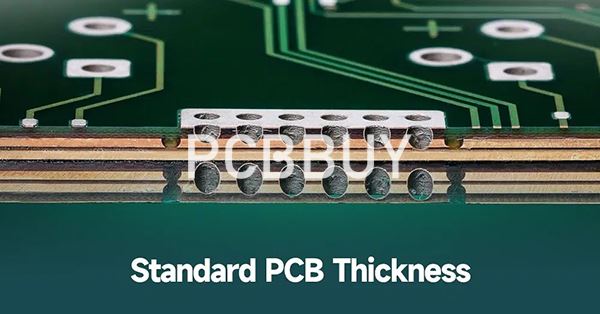
PCB thickness refers to the overall measurement from one surface of the board to the opposite side. Standard PCBs generally range from 0.8 mm to 1.6 mm, but advanced applications may require custom thicknesses. Variations in thickness can influence electrical performance, thermal management, and mechanical durability.
Importance of PCB Thickness
-
Electrical Characteristics: Impedance control depends on the thickness of the dielectric layers.
-
Structural Integrity: Thicker boards are more rigid, while thinner boards offer flexibility.
-
Thermal Management: Adequate thickness ensures effective heat dissipation in high-power applications.
What Defines PCB Thickness?
PCB thickness is determined by a combination of factors, including the type and number of layers, the thickness of copper traces, the dielectric material, and the solder mask. Standard PCB thickness is generally 1.6 mm, which caters to most consumer electronics, though it can range from 0.2 mm (ultra-thin) to over 3 mm for specialized applications.
Overview of Industry Standards
PCB manufacturers follow guidelines such as IPC-2221, which outlines standard thicknesses and tolerances for different applications. Typical configurations include single-layer, double-layer, and multilayer boards, with varying thicknesses depending on the number of layers and the intended use.
What Are the Factors Influencing PCB Thickness?
The thickness of a Printed Circuit Board (PCB) is influenced by a variety of factors that stem from its design requirements, manufacturing processes, and application-specific needs. Below is a detailed examination of these factors:
1. Number of Layers
-
Single-layer or Double-layer Boards: Typically thinner, as they involve fewer materials and simple configurations.
-
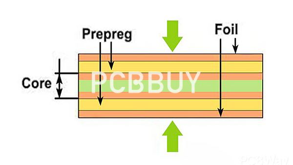
Multilayer Boards: Require additional layers of conductive and dielectric materials, leading to increased thickness.
2. Copper Thickness
The thickness of copper layers, measured in ounces per square foot (oz/ft²), significantly impacts overall PCB thickness.
Standard Thickness: Often 1 oz/ft² (35 μm).
Thicker Copper: Used for high-current applications, potentially increasing PCB thickness.
3. Dielectric Material
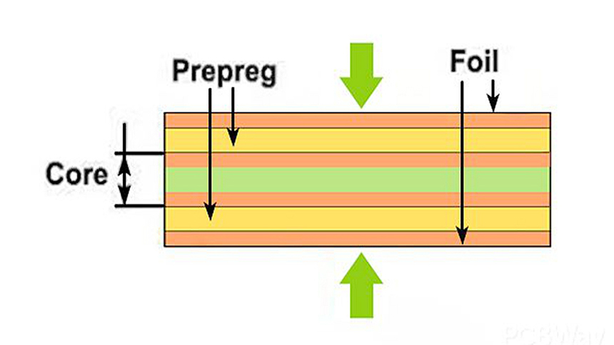
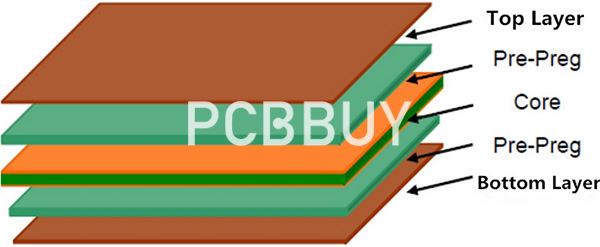
The core and prepreg (pre-impregnated composite fibers) layers define the dielectric thickness.
Material Selection: FR-4 (commonly used) or specialized materials like PTFE for RF boards affect the total thickness.
Dielectric constant and breakdown voltage requirements determine the material and its thickness.
4. Solder Mask
A solder mask is a thin layer of polymer applied to protect the PCB surface and prevent oxidation.
Although typically very thin (~10-50 μm), it contributes slightly to the overall thickness.
5. Impedance Control
High-frequency or high-speed circuits require controlled impedance.
The thickness of the dielectric material is often adjusted to achieve the desired impedance, thereby influencing overall board thickness.
6. Application Requirements
-
Flexibility: Flexible PCBs require thinner materials, while rigid PCBs might be thicker.
-
Power Handling: High-power applications demand thicker boards to handle heat dissipation and mechanical stress.
-
Compact Devices: Thinner PCBs are preferred for smartphones and wearables to save space.
7. Manufacturing Constraints
-
Drilling Capabilities: Thicker boards require advanced drilling techniques, especially for microvias or high-aspect-ratio holes.
-
Layer Bonding: The lamination process for multilayer PCBs must ensure uniform thickness, affecting the achievable total thickness.
8. Connector and Component Compatibility
The board’s thickness must align with component connectors and housing designs.
For instance, edge connectors often require a specific thickness for a secure fit.
9. Industry Standards and Tolerances
Industry guidelines such as IPC-2221 specify standard PCB thicknesses and acceptable tolerances.
Typical thickness ranges:
Single-layer Boards: 0.2–1.6 mm.
Multilayer Boards: 0.4–3.2 mm or more, depending on the number of layers.
10. Environmental and Mechanical Considerations
-
Thermal Management: Boards designed for high-temperature environments may need additional thickness to improve durability.
-
Mechanical Strength: Applications requiring rigidity, like automotive or industrial controls, favor thicker boards.
Key Example
Below is a sample table showing the relationship between PCB layer count and typical thickness ranges:
|
Layer Count |
Typical Thickness Range (mm) |
Common Applications |
|
Single-layer |
0.2–1.6 |
Consumer electronics |
|
Double-layer |
0.8–2.4 |
Power supplies, IoT devices |
|
4-layer |
1.2–3.2 |
Smartphones, complex circuits |
|
8-layer |
2.0–4.5 |
Servers, aerospace electronics |
By understanding these factors, engineers can optimize PCB thickness for functionality, manufacturability, and cost-effectiveness.
How to Measure PCB Thickness?
Direct Measurement
Use micrometers or calipers to measure the board's overall thickness. This is suitable for finished PCBs.
Design Software Analysis
PCB design tools, such as Altium or Eagle, provide thickness values during the design process. These values are based on predefined material stacks.
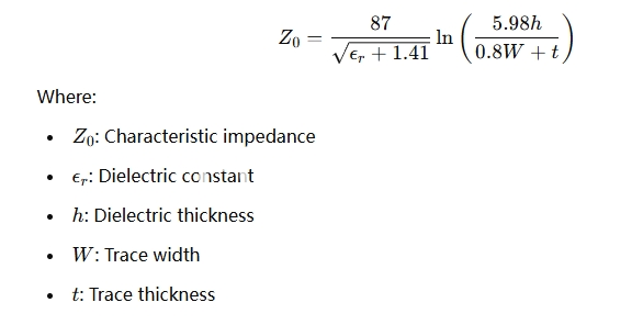
Impedance Calculations
Thickness is determined by electrical performance requirements, especially for impedance control.
What Are the Standard Thickness Options and Variability?
Industry Standards
-
IPC Guidelines: The IPC-2221 standard outlines standard PCB thicknesses and tolerances for various applications.
Custom Thickness
-
Some manufacturers support custom PCB thicknesses ranging from 0.2 mm (ultra-thin) to over 3.2 mm.
|
Application |
Recommended Thickness |
|
Mobile Devices |
0.4 - 0.8 mm |
|
Automotive Systems |
1.6 - 3.2 mm |
|
Aerospace/Defense |
2.0 - 4.0 mm |
What Are the Challenges in Determining PCB Thickness?
Material Constraints
Variations in dielectric materials and copper layers may lead to inconsistencies.
Impedance Matching
Ensuring proper impedance values while maintaining manufacturability is challenging.
Manufacturing Tolerances
Thickness tolerances can range between ±10% to ±20%, depending on the process and materials.
What Are the Future Trends in PCB Thickness Design?
Advanced Materials
Development of ultra-thin yet durable materials to support compact electronics.
Hybrid Designs
Combining rigid and flexible layers for mixed applications, such as foldable devices.
Enhanced Precision
AI-driven design tools will allow for more accurate thickness calculations based on application-specific requirements.
Conclusion
Determining PCB thickness is a multifaceted process that requires balancing electrical, mechanical, and thermal considerations. By understanding the materials, application demands, and manufacturing limitations, designers can optimize PCB thickness for functionality and durability. This critical step ensures that the final product meets performance and cost expectations.
Industry Category


