How to Drill PCB Board with 5 Tips in Manufacturing Process?
By:PCBBUY 10/13/2021 09:47

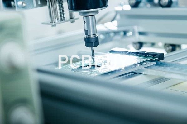
While there are many different types and styles of numerically controlled (NC) drilling machines used for printed circuit boards, the larger production versions can drill up to 30,000 holes per hour. These machines use automated optical guidance systems for precision and are equipped with multiple air-bearing spindles that can drill at speeds reaching 110,000 RPM.
The drill bits themselves are handled with automated changing systems and laser-inspected to ensure the maximum quality in the drilled holes. If you are going to learn the information of PCB drilling methods, please check and read the content below for more professional knowledge.
What are the 5 tips of PCB drilling?
1. What are the types of PCB drilling technologies?
Basically, there are two kinds of drilling technologies, mechanical and laser drilling. The mechanical drills have less precision but are easy to execute. This drilling technology implements drill bits. The smallest hole diameter that can be drilled by these drills is about 6 mils (0.006”).
The laser drills, on the other hand, can drill way smaller holes. Laser drilling is a non-contact process where the workpiece and the tool do not come in contact with each other. Here, the drill depth can be effortlessly controlled.
Laser drill limitations
A PCB is made UP of copper, glass fiber, and resin. These PCB materials have different optical properties. This makes it hard for the laser beam to burn through a board efficiently.
The life span of mechanical drills
The mechanical drills can be used for 800 hits when used on softer materials like FR4. For denser materials like Rogers, the lifespan is reduced to 200 counts. If a PCB maker ignores this then it will result in faulty holes which will turn the board to scrap.
If the designer understands the things that happen on the shop floor, he will have a better perception of how his design is brought to life. With this insight, the PCB designer ensures the designs are manufacturable. This, in turn, reduces the cost and the product can be delivered in a minimum turnkey time.

2. Drilling will affect the cost of PCB manufacturing
he cost of drillingwill be lower when the phase of drilling operation is performed at an optimum speed. In drilling the holes in the circuit board, every operation should go hand in hand. By drilling the holes faster, the speed should also be controlled to ensure the issues of tool breakage is not a problem. This controls the drill size to board thickness ratio. With this, by controlling the time consumed for pcb layout, cost can automatically be under control.
Thus, with the efforts to reduce cost, the research and development is also heading towards getting smooth conductivity between vias and have an effective component mounting with ensuring each drill has been successfully got registered and finished the tool path.
3. What are the types of PCB drilling via?
PCB drill holes can be classified according to whether they carry current or not. This categorization falls short of demonstrating the significance of drill holes within circuit board structures. A more thorough means of organizing or distinguishing between drill holes is according to their usage, as described below.
Through-hole vias
These holes are for routing traces from the top to the bottom surface. However, as these conductors extend throughout the board stackup, they can also be used to route signals between any layers, as needed.
Blind vias
Blind vias provide an electrical connection between a surface layer and an internal layer of the stackup. In contrast to through-hole vias, blind vias only extend to targeted layers.
Buried vias
Connections between internal layers that do not extend to either the top or bottom surfaces are referred to as buried vias.
Microvias
Microvias may be blind or buried. What distinguishes them from other vias is their small size, enabling their use in high-density signal routing.

4. How to drilling PCB in manufacturing process?
Drilling is one of the basic and most frequently performed processes in PCB manufacturing. There are many methods of creating micro-holes, such as conventional punches and dies, electrical discharge machining (EDM), vibration drilling, laser machining, and others.
We use electrical discharge machining in graphite-epoxy laminates since the graphite fibers are electrically conductive. Since the process generates high temperatures and currents that can lead to melting of the composite surface, thermal expansion of the graphite fibers, and debonding between fibers and the matrix, the production rate of the electrical discharge machining method is a bit slow.
5. What are the problems during PCB drilling?
Broken Drill Bit
Improper drilling nozzle, improper operation and insufficient bit speed or too high feed rate. When drilling, the depth of the spindle is too deep, resulting in poor chip removal of the drill nozzle and hanging.
Hole Loss
There is no aluminum sheet or reverse plate when drilling. The effective length of the drill tip can’t meet the needs of the thickness of the drill stack. The plate is special, which is caused by the front of the batch.
Plug Hole
The effective length of the bit is not enough. Substrate material problem. The backing plate is reused.
Missed Drilling
Program error. The program is deleted artificially or unintentionally. The data of drilling rig is not read.
Industry Category


