How to Improve Manufacturing Process with 4 PCB Troubleshooting Techniques?
By:PCBBUY 12/22/2021 09:13

PCB troubleshooting is a delicate process not only because the boards themselves are small in scale but because each of the individual components that comprises it is also sensitive. Repair techs must approach PCB maintenance with a keen eye for detail and mind for careful handling.
Are you a beginner of PCB industry? Do you know how to improve the manufacturing process? Please check and read the content below for more professional information.

1. What is the basic definition of PCB troubleshooting?
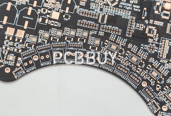
Printed circuit boards, or PCBs, are a mass of insulators and copper traces that connect densely packed components to create a modern circuit. Troubleshooting PCBs is often a challenge, with factors such as size, number of layers, signal analysis, and types of components playing a large role.
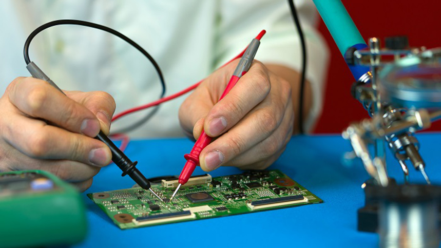
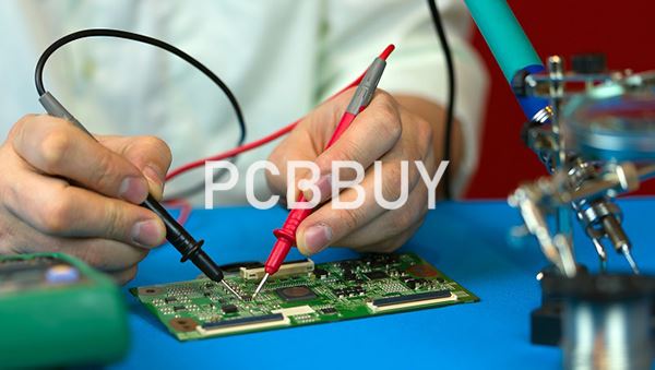
Some more complicated boards require specialized equipment to properly troubleshoot. However, most troubleshooting can be done with basic electronic equipment to follow traces, currents, and signals through the circuit.
It’s common for a fraction of fabricated PCBs to fail quality control tests. So PCB troubleshooting is usually the only way to salvage them. PCB troubleshooting is, therefore, a crucial cost-saving measure for PCB electronics fabrication. However, sometimes, it might be easier or cheaper to dispose of the malfunctioning device or replace it with a new one. That raises many questions concerning the scope of PCB troubleshooting.

2. How to process PCB troubleshooting?
The troubleshooting techniques we’ll see shortly are applicable on single layers, rigid/flex, digital analog, and radio frequency PCBs. But first, you’ll need to map out a PCB. This requires you to develop a clear understanding of its traces, signals, and current flow. Plus, you need to have the knowledge of which capacitor-resistor pairs are ideal to proceed with troubleshooting.
It will also help if you have a good grip on the filter, chole, and voltage divider position in the circuit board. However, suppose you don’t have a solid understanding of the configuration. In that case, it’s ideal to start the troubleshooting process from the connectors – the interface through which erroneous external inputs make their way into the circuit board. That said, you have to be good at mapping a PCB to continue without accessing the board’ schematics. This could eat up a lot of time, as every solder joint will need to be tested using a multimeter probe.
A better, more natural way to trace out PBCs is to use an aluminum piece. This method enables you to search for connections over a broader area per time, reducing the amount of effort and time involved. The process requires a piece of aluminum foil, a wire cutter, crocodile wire clips, and multimeter.

3. How to approaches for PCB troubleshooting?
To uncover the reason or reasons behind a PCB failure, it’s important to be methodical in troubleshooting and inspecting. Here are the four crucial steps to take — ranging from broad inspection to detailed troubleshooting — to get to the bottom of a PCB malfunction:
· Visual inspections — You can see a lot through a visual inspection. Burned or eroded components are the easiest to spot, which signal overheating issues or chemical fluid leakage as reasons for malfunction. You can also identify missing components, indicating a flawed or defective board. Finally, clean away debris before probing the board deeper for issues.
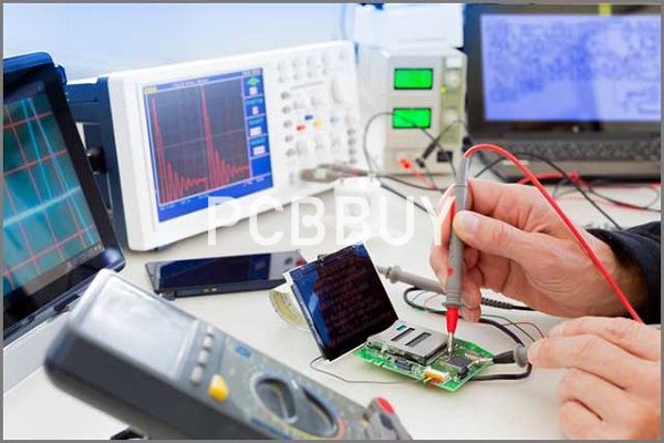
· Physical inspections — With the board under load, a physical inspection may yield additional insights. Hot spots are easy to feel, which can signal potential burnt components that may not be visually identifiable. Probing with an oscilloscope can also help detect impedance issues resulting from age-related power problems.
· Component testing — Delving deeper into the PCB’s many components, you can test the integrity of batteries, capacitors, resistors, inductors, diodes, switches, and transistors. Use a multimeter to compare values to factory standards to spot discrepancies. Often, it’s these individual components that fail and eventually lead to larger failures of the entire PCB.
· Integrated circuit testing — A final stage of PCB troubleshooting involves testing integrated circuits (ICs). An oscilloscope also comes in handy here. Unfortunately, it can be difficult to test ICs, depending on how many are present on a PCB or the nature of the circuit itself. The best approach is to identify a known good circuit and test all ICs against it to recognize problematic ones.
4. What are the necessary tools of PCB troubleshooting?
The tools you’ll need to troubleshoot circuit boards will depend on the complexity of the design. Basic troubleshooting may require only a digital multimeter, while intricate or component-dense PCBs require specialised test equipment, such as oscilloscopes, logic analysers, and LCR meters.
Some basic tools for carrying out PCB repairs include:
· A clamp
· A hot air gun
· Tweezers
· Copper braids
· Isopropyl alcohol (ISP)
· Wipes, and
· Soldering equipment
Industry Category


