How to Remove the Drilling Dirt after PCB Drilling?
By:PCBBUY 04/19/2024 11:33

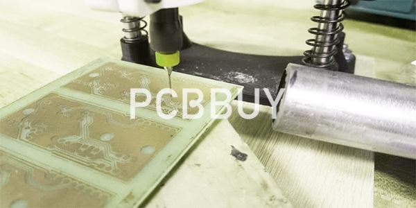
In the manufacturing process of printed circuit boards, whether it is a rigid printed circuit board or a flexible printed circuit board, energy will be generated on the hole wall after drilling. The production of guiding is determined by the material composition of the printed circuit board, and the following is to analyze the reasons for the drilling pollution of the two boards from its composition.
The glass conversion temperature of epoxy resin or epoxy glass fiber cloth in rigid printed circuit boards is between 110 and 180 ° C, and the glass conversion temperature of bichic acid or epoxy thermosetting film in flexible printed circuit boards is about 120 ° C. During the drilling process, due to various reasons, the temperature of the drill bit will reach more than 200 ° C, which will melt the epoxy resin, epoxy glass fiber cloth acrylic or epoxy adhesive film in the drilling, and then adhere to the hole wall with copper debris and polyimide debris to form greasy. If the copper is not cleaned before sinking, it will not sink the copper and cause an open circuit, resulting in a large number of scrap boards. Therefore, the removal of drilling dirt is a very important process.

At present, there are many methods to remove drilling dirt, including dry method and wet method. Kilo fold treatment is to remove the drilling dirt in the hole wall by plasma under vacuum environment. This method requires specialized plasma processing equipment, high processing cost, and is generally used in the processing of flexible multilayer printed circuit boards, rigid flexible bonded multi-layer printed circuit boards, polyimide multilayer printed circuit boards and rigid layer printed circuit boards with small apertures. Wet treatment includes concentrated sulfuric acid, concentrated acid, potassium permanganate and PI (polyimide) adjustment treatment, chromic acid decontamination due to serious environmental pollution problems, now basically no one used. The commonly used treatment methods are concentrated sulfuric acid, broken potassium permanganate treatment, PI adjustment treatment is being studied, and has achieved good results. Concentrated sulfuric acid method and alkaline potassium permanganate method are used to deal with rigid printed circuit boards, and PI adjustment method is used to deal with flexible printed circuit boards. Each of these treatments is described below.
How to Remove the Drilling Dirt with Plasma treatment?
1. Principle of plasma removal of drilling dirt and erosion
Plasma decontamination is a foreign technology that began to be used in the 1980s. Plasma is an ionized gas, which is electrically neutral as a whole, and is an ionized state composed of charged particles, called the fourth state of matter. The application of plasma to remove the drilling dirt from the hole wall of the rigid printed circuit board and the flexible printed circuit board can be regarded as a dynamic chemical reaction process in which the highly activated plasma gas reacts with the chemical powder of the hole wall and the Ming fiber, and the generated gas products and some non-reactive particles are discharged into the secret extraction system. The conditions for the generation of plasma gas are:
a. Vacuum a grain (26.66~66.66Pa) and maintain a certain vacuum degree;
b. Pass the selected gas into the vacuum container, and a certain vacuum degree must be maintained:
c. Turn on the radio frequency power supply to apply a high frequency and high voltage electric field between the positive and negative electrodes in the vacuum, the gas is ionized between the positive and negative electrodes, emit glow, and form plasma. At this time, the gas is continuously input, and the vacuum pump has been working to maintain a certain vacuum degree in the vacuum. Since plasma treatment requires specialized equipment and electronic-grade gases, it is expensive to use plasma to remove drilling dents.
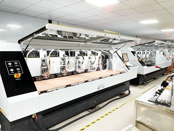
2. Plasma removal of drilling erosion system
Printed circuit board special plasma chemical treatment system - plasma decontamination and erosion system, generally composed of five parts: vacuum chamber, vacuum pump, radio frequency (RF) generator, microcomputer controller, original gas. Each type of plasma treatment equipment is only slightly different in the structure of the electrode in the vacuum chamber and the position and mode of gas delivery.
3. Plasma treatment process
(1) High pressure wet sand blasting
High pressure wet sandblasting is a process of cleaning the hole wall of multi-layer printed circuit board with corundum (Al4 O2) with particle size of about F600 under high pressure water. High pressure washing and wet sandblasting are used to provide clean pore walls and reduce the load of subsequent plasma treatment.
(2) Baking board
The drying board is mainly to remove the moisture in the processing board. Because the moisture absorption rate of acrylic resin and polyimide resin is much larger than that of epoxy resin, if the moisture in the printed circuit board enters the vacuum system due to low vacuum, it will inevitably reduce the vacuum degree and condense in the vacuum pump, which will cause great damage to the vacuum pump. In addition, the chemical activity of the plasma is also affected. The process conditions of the drying plate are 3~4h at 120℃.
(3) Plasma quadruple etching treatment
The whole plasma treatment process is batch intermittent operation, which is divided into three stages. The first
In the first stage, high purity nitrogen (N2) is used as the treatment gas to produce plasma. The goal is to have the whole system in N to surround; N, the free radical reacts with the gas molecules attached to the pore wall, so that the pore wall is clean, while preheating the printed circuit board, so that the polymer material is in a certain activated state, so as to facilitate the subsequent stage of reaction.
In the second stage, O2 CF4 Is used as the original gas, and O2 F plasma is produced after mixing, which reacts with acrylic acid, polyimide, epoxy resin and glass fiber to achieve the purpose of removing drilling stains and pits. In the third stage, O is used as the original gas, and the generated plasma reacts with the reaction residue to clean the pore wall. The process parameters of plasma treatment mainly include: gas ratio, flow rate, RF power, vacuum degree and treatment time. The gas ratio is an important parameter to determine the activity of generating plasma. To achieve a better treatment effect, generally O2 50%~90% (volume fraction) and CF4 50%~10% (volume fraction). In pure O2 the plasma reacts slowly with the pore wall material and generates large heat, resulting in the oxidation of copper. And 50% ~10% (volume fraction) of CF4 increase the reaction rate of quadruple corrosion, can produce high polarization, strong activity of oxygen fluorine free radicals. Radio frequency (RF) power is between 2 and 5kw. The high power increases the ionization degree of the gas and improves the reaction speed, but at the same time it also generates a lot of heat, thereby increasing the number of intermittent reactions.
The gas pressure of the system is mainly determined by the RF power, gas flow and proportion. At lower pressure, the plasma discharge is not uniform, but the mean free path of particles increases, which increases the ability of particles to enter the small hole. High gas pressure reduces the permeability of particles and produces a lot of group light. Increasing the power level can improve the permeability. The ideal system pressure is between 26.66 and 40.00Pa.
O2 +CF is taken as an example to illustrate the reaction.
1) Formation of plasma:
O2+ CF2→0 +OF+CO + COF +F+e+……
2) Plasma reaction with polymer materials (C, H, O, N) :
(C, H, O, N) +(O+OF+CO +COF+F+e+...) →CO2↑ +H2O↑ + NO2↑+...
3) If there is a glass fiber cloth composed of Si and SiO2, the reaction is as follows:
HF + Si→SiF4↑ +H2↑
HF + SiO2 →SiF4↑ +H2O↑
The above is not only the basic principle of plasma removal drilling surface cleaning, but also the basic principle of plasma system as a micro through hole.
The plasma removal of drilling dirt is a complex physicochemical process, which has many influencing factors, including process parameters, drilling quality, pre-treatment effect, PCB board humidity and temperature, and the distribution and size of holes on the PCB. In short, only by fully considering all kinds of influencing factors and correctly determining the process parameters of pre-treatment and plasma treatment, can the quality of drilling dirt and erosion removal be ensured.
(4) Remove the glass fiber
When plasma is used to remove the drilling dirt in the holes of flexible and rigid printed circuit boards, the erosion rate of various materials varies, in the order of greatest to smallest: acrylic film, epoxy resin, polyimide, glass fiber and copper. Protruding glass fiber heads and copper rings are clearly seen in the microscope. In order to ensure that the electroless copper plating solution can fully contact the pore wall, so that the copper layer does not produce voids and voids, it is necessary to remove the residues of the plasma reaction on the pore wall, the protruding glass fiber and the polyimide film, the treatment methods include chemical and mechanical methods or a combination of both. The chemical method is to soak the printed circuit board with hydrogen fluoride solution, and then adjust the charging property of the hole wall with ionic surfactant (KOH solution). Mechanical methods include high pressure wet blasting and high pressure water washing. The combination of chemical and mechanical methods is the best.
How to Remove the Drilling Dirt with Concentrated Sulfuric Acid Treatment?
Due to the strong oxidation and water absorption of concentrated H2SO4 the epoxy resin can be carbonized and formed into water-soluble alkyl sulfonates and removed.
The effect of decontamination is related to the concentration of H2SO4 treatment time and the temperature of the liquid. The concentration of SO2 Used for decontamination shall not be lower than 86%, and the treatment shall be 20~40s at room temperature. If the corrosion is to be desired, the solution temperature should be appropriately increased and the treatment time should be extended.
Concentrated H2SO4 only works on the epoxy resin of the pore wall, and has no effect on the glass fiber. After the use of concentrated H2SO4 four-etched multilayer printed circuit boards, the glass fiber head will protrude in the hole wall, requiring fluoride (such as ammonium hydrogen fluoride or hydrofluoric acid) treatment. When using fluoride to treat protruding glass fiber heads, attention should also be paid to controlling process conditions to prevent Wicking due to glass fiber corrosion. The following processes are commonly used:
|
Thick H2SO4 |
10mL/L |
|
NH4 HF2 |
5~10g/L |
|
Temperature |
30℃ |
|
Time |
3 to 5 min |
Due to the concentration of H2SO4 dissolve the epoxy resin, the resin surface of the hole wall becomes too smooth, so that the binding force of the electroless copper plating layer is affected, so the alkaline potassium permanganate treatment method is developed.
How to Remove the Drilling Dirt with Alkaline Potassium Permanganate Treatment?
By this method, the drilling dirt of epoxy resin can be removed, and the surface of epoxy resin can be etched to produce small, uneven pits on the surface to improve the surface roughness, so as to increase the binding force between the hole wall coating and the substrate. In the electroless plating process, the adsorption amount of the activator is effectively increased, and the phenomenon of hole holes and blowing holes is greatly reduced. Alkaline potassium permanganate treatment is carried out in the following three ways.
1. Swelling
Objective: To swell epoxy resin and soften it to prepare for the removal of drilling dirt by potassium permanganate.
Recipe:
|
Sodium hydroxide |
20g/L |
|
Hexanediol ether |
30g/L |
|
Hexadiol |
2g/L |
|
Water |
The rest |
|
Temperature |
60 ~ 80 ℃ |
|
Time |
5min |
Epoxy resin is a highly polymerized compound with excellent corrosion resistance. Its corrosion forms are mainly dissolution, swelling and chemical cracking (such as concentrated sulfuric acid on epoxy resin is mainly dissolved, its concave corrosion is very obvious). According to the empirical law of "similar phase bath", ether organic matter is generally weak in polarity, and has a similar molecular structure with epoxy resin (R-0-R), so it has a certain solubility to epoxy resin. Because ether can hydrogen bond with water, it has a certain solubility in water. Therefore, water-soluble ether organic compounds are commonly used as swelling agents to remove drilling dirt. The content of sodium hydroxide in the swelling solution should not be too high, otherwise, the ammonia bond association will be destroyed and the organic chain phase will be separated. In production, this method is commonly used to analyze the content of swelling agent.
2. Remove drill stain
Objective: To make use of the strong oxidation of potassium permanganate to drill and oxidize the swelling and softening epoxy resin.
Recipe:
|
NaOH |
35g/L |
|
KMnO4 |
55gL |
|
NaCIO |
0.5g/L |
|
Temperature |
75℃ |
|
Time |
10min |
Potassium permanganate is a strong oxidizing agent, which is reduced to Mn* in a strong acidic solution. In neutral and weakly alkaline environments, it is reduced to MnO; When the concentration of NaOH is greater than 2mol/L, it is reduced to Mn0. -. Potassium homobaht has stronger oxidation ability in strong acidic environment, but the reaction rate of oxidizing organic matter under alkaline condition is faster than that under acidic condition.
Under high temperature and alkaline conditions, potassium permanganate oxidizes and cracks the carbon chain of epoxy resin:
4MnO4+C (epoxy resin) +40H-=4MnO42 +CO2(g)+2H2O
Restore
Objective: To remove potassium permanganate, potassium manganate and manganese dioxide from drilling residue.
Recipe:
|
H2SO4 |
100mL/L |
|
NaC2 O4 |
30g/L |
|
Temperature |
40℃ |
Manganese ion is a heavy metal ion, its existence will cause "poisoning", so that the ion or atom lose activation activity, resulting in the failure of hole metallization. Therefore, the presence of manganese must be removed before electroless copper plating.
It can be seen from the above reaction that potassium permanganate, potassium magnate and manganese dioxide remaining in drilling dirt on PCB product can be completely removed through the reduction step.
How to Remove the Drilling Dirt with PI Adjustment Method?
The PI adjustment method can remove the polyimide drilling dirt, and can quadruple the 1~3μm thick polyimide layer, so that the copper layer and the hole wall produce three-dimensional combination, the binding force is firm. The electrification of the pore wall is adjusted to increase the adsorption capacity of the activator. The treatment steps are: dip deionized water →PI adjustment treatment to remove drilling dirt and water washing.
1. Dip in deionized water
Since PI adjustment solution will precipitate under the action of tap water, it is necessary to soak in deionized water before soaking the treatment solution to remove some drilling dirt and tap water to ensure the quality of PI adjustment solution and extend its use time.
2. PI adjustment treatment to remove drilling stains
PI adjustment solution contains hydrazine, additives, etc., during the treatment of the additives to polyimide and acrylic film greasy swelling, so that it is easy to be decomposed and removed. The polyimide stain is then decomposed by reaction with hydrazine to remove the corresponding stain. The quality of the removal of drilling dirt is closely related to the content of each component in the solution, the temperature of the solution and the action time, and only in strict accordance with the formula and process parameters can we get a good product and a high pass rate.
PI adjustment liquid formula and process parameters:
|
PI stock solution |
40mL/L |
|
Additive |
40g/L |
|
Temperature |
35℃ ±5℃ |
|
Time |
3min |
3. Wash
After removing the drilling dirt, it should be fully cleaned to prevent the PI adjustment liquid from being carried to the next process and affecting the quality of the sunk copper; Or pigen
The liquid remains in the hole, resulting in excessive biting and excessive swelling of the film. In a word, using PI adjustment solution to remove drilling dirt is a good method to remove drilling dirt of flexible printed circuit board.
Reference
He Wei, PCB Basic Electrical Information Science and Technoloy, China Machine Press,86-92
Industry Category


