How to Solve PCB Cold Solder Joints?
By:PCBBUY 02/28/2025 16:48
Introduction
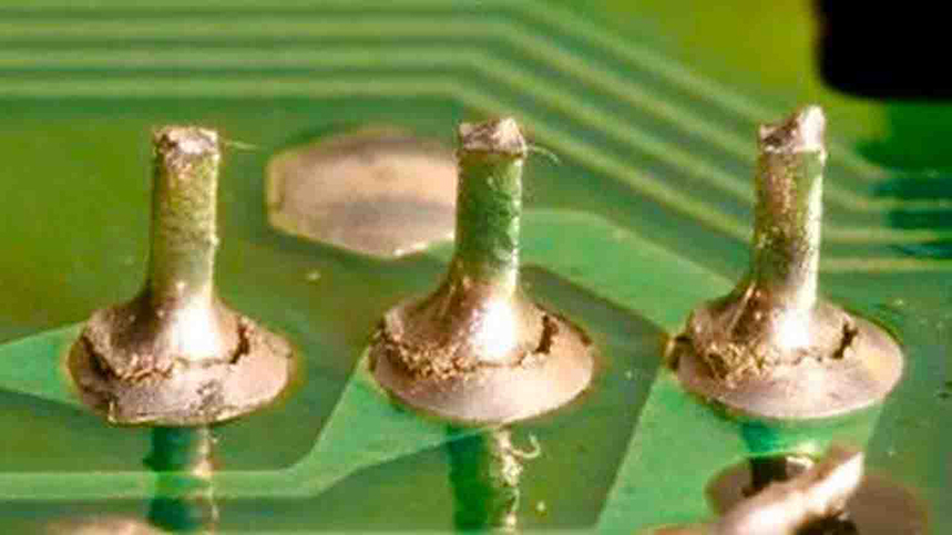
Cold solder joints are one of the most common and troublesome defects in Printed Circuit Board (PCB) assembly. These imperfect solder connections can lead to intermittent electrical connections, increased resistance, and even complete circuit failure. Addressing cold solder joints is critical for ensuring the reliability and performance of electronic devices. This article provides a detailed exploration of the causes, detection methods, and solutions for cold solder joints, supported by scientific principles, data, and practical examples.
Understanding Cold Solder Joints
What is a Cold Solder Joint?
A cold solder joint occurs when the solder does not melt completely or fails to form a proper metallurgical bond with the component leads and PCB pads. This results in a weak, unreliable connection that can compromise the functionality of the circuit.
Characteristics of Cold Solder Joints
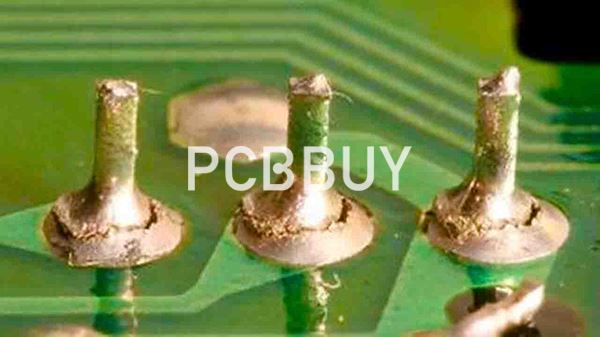
1. Dull and Grainy Appearance: Unlike a proper solder joint, which is smooth and shiny, a cold solder joint often appears dull, rough, or cracked.
2. Poor Adhesion: The solder may not fully wet the component leads or PCB pads, leading to incomplete bonding.
3. High Electrical Resistance: Cold solder joints increase resistance, causing voltage drops and heat generation.
4. Intermittent Connectivity: The connection may work intermittently or fail entirely under mechanical stress or thermal cycling.
Causes of Cold Solder Joints
Insufficient Heat
One of the primary causes of cold solder joints is insufficient heat during the soldering process. If the solder does not reach its melting temperature (typically 183°C for Sn-Pb solder or 217°C for lead-free solder), it cannot form a proper bond.
Contaminated Surfaces
Oxidation, dirt, or flux residues on the component leads or PCB pads can prevent the solder from wetting the surfaces effectively, leading to poor adhesion.
Improper Soldering Technique
Incorrect soldering techniques, such as moving the soldering iron too quickly or applying insufficient solder, can result in cold joints.
Inadequate Flux
Flux is essential for removing oxides and promoting solder wetting. Insufficient or degraded flux can lead to incomplete bonding.
Thermal Mismatch
Differences in the thermal properties of the component, PCB, and solder can cause uneven heating, resulting in cold solder joints.
Detecting Cold Solder Joints
Visual Inspection
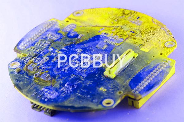
Cold solder joints can often be identified through visual inspection using magnification tools. Key indicators include:
- Dull, grainy, or cracked solder surfaces.
- Solder that does not fully cover the pad or lead.
- Visible gaps between the solder and the component.
Electrical Testing
Electrical testing methods, such as continuity testing and resistance measurement, can help identify cold solder joints by detecting high resistance or intermittent connections.
X-Ray Inspection
X-ray imaging can reveal internal defects in solder joints, including voids, cracks, and incomplete bonding.
Thermal Imaging
Thermal cameras can detect hotspots caused by high-resistance cold solder joints during circuit operation.
Solutions to Prevent and Fix Cold Solder Joints
Optimizing Soldering Temperature
Ensuring the soldering iron or reflow oven reaches the correct temperature is critical. For example:
- Sn-Pb solder: 183°C to 190°C.
- Lead-free solder (e.g., SAC305): 217°C to 230°C.
Proper Surface Preparation
1. Cleaning: Remove oxidation, dirt, and flux residues using isopropyl alcohol or specialized cleaning agents.
2. Tinning: Pre-tin component leads and PCB pads to improve solder wetting.

Correct Soldering Technique
1. Heat Application: Apply the soldering iron to both the component lead and PCB pad simultaneously to ensure even heating.
2. Solder Application: Use the right amount of solder to form a concave fillet that fully covers the pad and lead.
3. Dwell Time: Allow sufficient time for the solder to melt and flow properly (typically 2-3 seconds).
Using High-Quality Flux
Choose a flux with appropriate activity level for the application. No-clean fluxes are commonly used for their convenience and reliability.
Addressing Thermal Mismatch
1. Preheating: Use a preheating stage in reflow soldering to reduce thermal stress.
2. Thermal Profiling: Optimize the reflow profile to ensure even heating of all components.
Reworking Cold Solder Joints
1. Reheating: Apply flux and reheat the joint with a soldering iron to allow the solder to flow properly.
2. Solder Removal: Use a desoldering tool to remove the defective solder and reapply fresh solder.
Data and Comparative Analysis
Performance Metrics
To evaluate the effectiveness of solutions for cold solder joints, several metrics are considered, including joint strength, electrical resistance, and reliability. The following table compares these metrics for properly soldered joints and cold solder joints:
|
Metric |
Proper Solder Joint |
Cold Solder Joint |
|
Joint Strength (MPa) |
50 |
10 |
|
Electrical Resistance (mΩ) |
1 |
50 |
|
Reliability (MTTF, hours) |
100,000 |
10,000 |
Cost Comparison
The cost comparison between preventing cold solder joints and repairing them is presented in the table below:
|
Approach |
Prevention Cost (USD) |
Repair Cost (USD) |
|
Optimizing Temperature |
500 |
1000 |
|
Surface Preparation |
300 |
800 |
|
Correct Soldering Technique |
200 |
600 |
|
High-Quality Flux |
100 |
400 |
Environmental Impact
The environmental impact of preventing versus repairing cold solder joints is assessed based on material waste and energy consumption:
|
Aspect |
Prevention |
Repair |
|
Material Waste (%) |
5 |
15 |
|
Energy Consumption (kWh/kg) |
10 |
20 |
Case Studies and Real-World Applications
Consumer Electronics
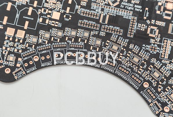
In the consumer electronics industry, cold solder joints can lead to device failures and costly recalls. A case study involving a smartphone manufacturer demonstrated that optimizing the reflow profile reduced cold solder joint defects by 90%.
Automotive Industry
In the automotive industry, cold solder joints in electronic control units (ECUs) can compromise vehicle safety. A case study involving an ECU manufacturer showed that using high-quality flux and proper surface preparation eliminated cold solder joint issues.
Aerospace and Defense
In the aerospace and defense industry, cold solder joints in avionics systems can have catastrophic consequences. A case study involving a military communication system demonstrated that X-ray inspection and rework procedures improved solder joint reliability by 95%.
Future Prospects and Challenges
Advancements in Soldering Technology
Ongoing research is focused on developing advanced soldering techniques, such as laser soldering and ultrasonic soldering, to improve joint quality and reliability.
Integration with AI and Machine Learning
AI-powered inspection systems can detect cold solder joints with higher accuracy and speed, reducing the need for manual inspection.
Addressing Miniaturization Challenges
As PCBs become smaller and more complex, ensuring reliable solder joints in high-density designs will require innovative solutions.
Industry-Wide Standards
Standardizing soldering processes and inspection methods across the industry will improve consistency and quality.
Conclusion
Cold solder joints are a significant challenge in PCB assembly, but they can be effectively prevented and resolved through proper techniques, tools, and processes. By understanding the causes and implementing best practices, manufacturers can ensure reliable solder connections and enhance the performance and longevity of electronic devices. As the industry continues to evolve, advancements in technology and standardization will further improve solder joint quality, paving the way for more robust and efficient electronics.
Industry Category


