How to use blank PCB board?
By:PCBBUY 06/18/2021 17:31

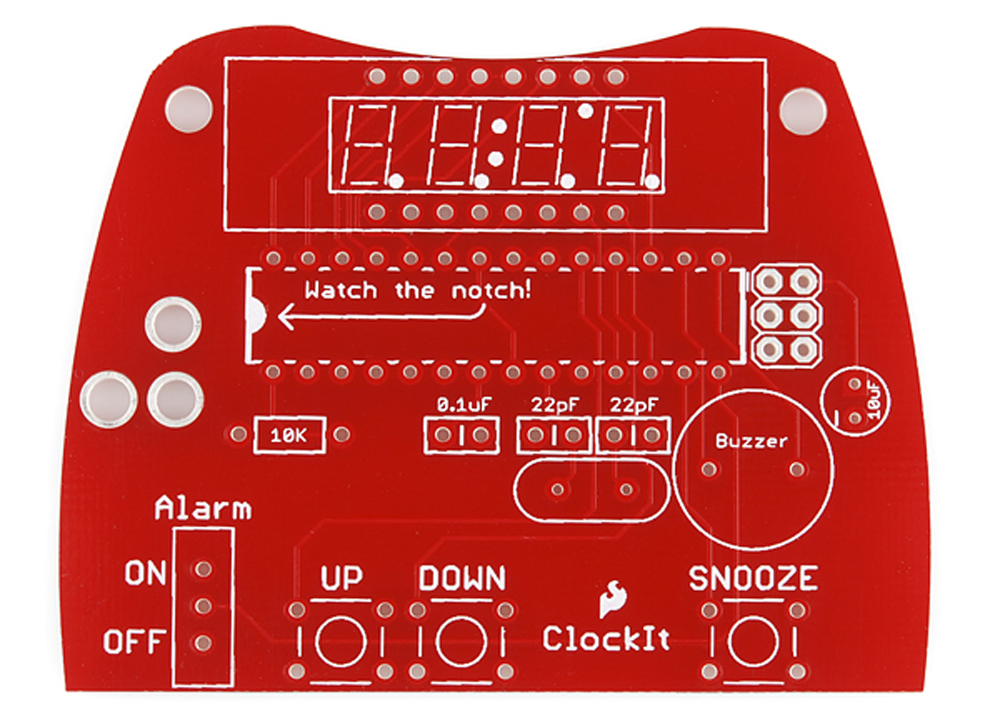
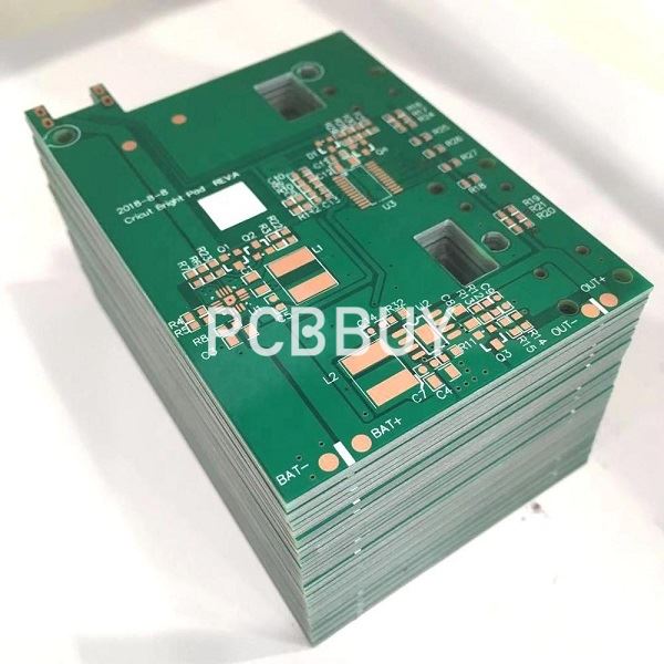
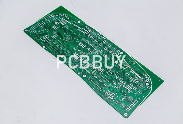
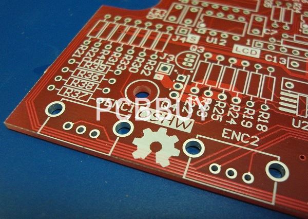
Recent years, technological advancements have brought about significant progress in the design and manufacturing of Blank PCB. As the main component of our electronic equipments, we can’t live without blank PCB of electronic equipment in our daily life. In this passage you will get into everything about blank PCB board, come and check for more information.
How to create a blank PCB board?
Designing a Blank PCB board can be a rather tedious job as it requires adequate technical knowledge and expertise to get it right. If you plan on using your PCB board for commercial purposes, it becomes even more critical to get the specs right.

The process of correctly designing a Blank PCB board is a lot simpler than most people believe. With the right tools and basic knowledge, you can effectively create a functional blank PCB board that will meet your electrical requirements. Using a CAD tool will make the design of your Blank PCB board easily achievable. We will review the powerful Autodesk tool “EAGLE” used for designing printed circuit boards.
·Getting Started
·Designing Your Blank PCB Board Schematic
·Blank PCB Board Layout Design
The steps above are the basic skills needed to create a Blank PCB board using the Eagle software. It allows you to detail the specific requirements for your PCB board according to the electronic needs.
How to use blank PCB board?
A blank PCB board is essentially the foundation for all the components that will make up a functional printed circuit for an electronic device. It serves as a blank slate for placing essential components. A Blank PCB board is useless without the necessary components to make it fulfill its primary purpose. Batteries, resistors, transistors, capacitors, and LEDs are components that go onto a blank PCB board.
The process of adding components to a Blank PCB board is known as Mounting Technology. There are essentially two mounting technologies when adding components to PCB in use today. They are:
Surface Mount Technology (SMT)
Surface mount technology is an electronic assembly method in which electronic components mounted on a blank PCB board's surface. SMT eliminates the need for drilling holes on a PCB board. It is a mounting technique that efficiently uses space; therefore, it significantly reduces manufacturing costs.
SMT has enabled engineers to build highly complex electronic circuits with minimum footprints. A high level of complexity is achievable with devices that are vastly smaller than their intended purposes. SMT is arguably the most common form of mounting technology in the industry today. Engineers, designers, and manufacturers favor SMT for their printed circuit board assembly (PCBA) processes.
What are the advantages?
• Allows for higher component density (i.e., more components fit into a relatively small area)
• Components can be placed on both sides of the blank PCB board
• Performance is not affected by conditions such as shaking and vibrations
• Production costs are much lower
• Circuit production is fast, consistent, and saves time for the manufacturer
• Less drilling; as drilling takes up a considerable amount of time
• It is the best option when there is a limited amount of space available for mounting components
What are the disadvantages?
• It is highly susceptible to damage from harsh thermal conditions
• It is unsuitable for high-power, high-voltage, and large components.
• It is complicated to manually repair boards using surface mount technology; due to the components' small size.
• It can be unsuitable for components that frequently require connecting and disconnecting.
Through-Hole Technology
Through-hole technology (THT) is the other type of mounting technology used in PCB boards' production. It involves drilling holes in the blank PCB board through which engineers insert leads for placing the components on the board. The leads soldered to pads on the other side of the board.
THT carries a distinct advantage over SMT because it is more durable and functions excellently under extreme conditions. While SMT is unable to handle high voltage and thermal conditions, THT performs perfectly. This unique feature makes it a preferred choice for high-power uses and military applications.

What are the advantages?
• THT is the ideal choice for larger circuits that will undergo high power, voltage, and mechanical stress
• It is more reliable when compared to SMT because of the components bond to the blank PCB board strongly
• PCB boards using THT technology are more straightforward to prototype
• It is perfect for systems that require a high heat tolerance
• It is the preferred choice for circuits that have military and aerospace applications
What are the disadvantages?
• Cost of production can be high due to the need for drilling holes in the plank PCB board
• The assembly process tends to be more complicated than SMT technologies
• The speed of production is usually slower
• Board size is hard to minimize due to the need to drill multiple holes through the board for components
These two mounting technologies are the pillars that drive the PCB manufacturing industry. It’s time to look into how the components are attached to the blank PCB board itself.

How to connect components to blank PCB board?
Although connecting components to a PCB board is called mounting technology, the process itself is called soldering. On the flip side, the process of detaching components from a PCB board is called Desoldering. Let's look at these terms in more detail.
Soldering
Soldering is when two or more items are joined together by melting a filler material (solder) between them. Unlike welding, which involves melting the joint pieces, Soldering is a preferable option since the electrical parts won't get destroyed in the joining process.
The solder material is usually a metal alloy with a much lower melting point than the components bonded together. For electrical purposes, it is preferable to use a solder material with high electrical conductivity. A soldering iron is a primary tool to be used for the process. There are complex machines that ensure a high quality of solder connections in electronic circuits for industrial production purposes.
Desoldering
Put, it is the opposite of Soldering. Desoldering is the process of removing solder connections, the solder material, and components from a circuit board for repair, replacement, and salvage.
The main instrument used for the process is the desoldering pump. Some additional materials used in the process include heat guns, solder wick, heated soldering tweezers, removal alloys, and removal fluxes.
Industry Category


