
How Can Manufacturers Improve Microvia Yield in HDI PCB Manufacturing?
By:PCBBUY 09/28/2026 15:17

Microvias are fundamental to high-density interconnect (HDI) PCB technology. They allow designers to create compact interconnections between buildup layers and are particularly useful for fine-pitch BGA packages, high-density routing, and space-constrained electronic products.
However, shrinking the microvia diameter does not automatically result in a better HDI design. As dimensions become smaller, manufacturing margins become narrower and variations in laser drilling, desmear, registration, plating, filling, and lamination become increasingly important.
Therefore, microvia yield improvement in HDI PCB manufacturing should be approached as a complete process-control problem. From an experienced PCB manufacturing perspective, the objective is not simply to produce smaller microvias, but to produce them consistently across the entire panel and throughout volume production.
This is particularly relevant to automotive electronics, industrial control, power equipment, energy storage, new-energy systems, and embodied robotics, where HDI structures may need to coexist with high-density components and demanding reliability requirements.

1. What Causes Microvia Yield Problems?
Microvia defects can originate from different stages of the manufacturing process. A defect observed during electrical testing may actually have originated much earlier during laser drilling or lamination.
Common risk areas include:
-
Laser drilling variation
-
Resin or debris remaining inside the microvia
-
Poor target-pad surface condition
-
Microvia-to-target-pad misregistration
-
Inconsistent copper deposition
-
Voids or incomplete filling
-
Excessive variation in dielectric thickness
-
Lamination movement
-
Inadequate process margin in the original PCB design
Microvia reliability is particularly sensitive to interfaces between copper and dielectric materials and between different copper layers. Thermal and mechanical stresses can cause defects at these interfaces to develop into cracks or separation during assembly or service.
Consequently, improving yield requires identifying the process step that creates the defect rather than relying only on final electrical testing to screen it out.
2. How Does Laser Drilling Affect Microvia Yield?
Laser drilling is one of the first critical steps in microvia formation.
The laser must remove the dielectric material without unnecessarily damaging the underlying copper target pad. Variations in laser energy, focus, pulse conditions, dielectric thickness, and material characteristics can influence the resulting via geometry.
Potential problems include:
-
Incomplete dielectric removal
-
Excessive ablation
-
Irregular via profiles
-
Resin residue
-
Target-pad damage
-
Variation in via diameter or depth
The laser process therefore needs to be matched to the actual dielectric system and buildup structure.
Designers can also improve manufacturing margin by avoiding unnecessarily aggressive microvia dimensions. If a slightly larger via can provide sufficient routing density, it may offer a more forgiving process window than pushing the geometry to the smallest possible value.
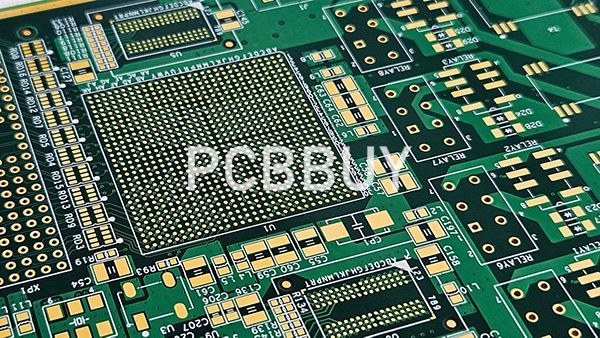
PCBBUY supports laser blind vias down to approximately Φ0.075 mm. This is a manufacturing capability, not a recommendation that every design should use the minimum diameter. The practical microvia size should be determined from the stackup, dielectric thickness, target-pad structure, routing density, and reliability requirements.
3. Why Is Desmear Important for Microvia Yield?
Laser ablation can leave resin residues on the via wall or target-pad surface. If these residues are not properly removed, they can interfere with subsequent metallization.
The resulting interface may have insufficient bonding quality or inconsistent copper coverage.
A reliable HDI process therefore needs appropriate surface preparation before copper deposition.
The key objective is to achieve a clean and consistent surface while avoiding excessive treatment that could damage the dielectric or copper target.
This is particularly important for small microvias because the available surface area and process margin are limited. Research and industry process studies identify incomplete desmear and poor interface preparation as important contributors to microvia reliability problems.
4. How Does Copper Plating Influence Microvia Yield?
Copper plating is another major factor in microvia quality.
After laser drilling and surface preparation, the microvia needs a continuous conductive structure that can withstand electrical and mechanical stresses.
Potential plating-related problems include:
-
Insufficient copper deposition
-
Non-uniform deposition
-
Voids
-
Poor connection at the target pad
-
Inadequate filling
-
Localized weak areas
These defects may not always be obvious from a simple visual inspection. A microvia can initially provide electrical continuity while still containing a structural weakness that becomes significant after thermal cycling.
For this reason, plating parameters should be controlled according to the actual via geometry and material system. The goal is consistent metallization rather than simply maximizing copper thickness.
5. Why Is Registration Critical to Microvia Yield?
A microvia must land correctly on its target pad.
This sounds straightforward, but sequential lamination introduces dimensional changes, and every additional buildup layer creates another registration relationship.
The relevant alignment chain can be expressed as:
Laser microvia → capture pad → inner-layer trace → underlying via structure
If the microvia is positioned too close to the edge of the target pad, the effective landing area decreases. In stacked structures, cumulative alignment variation becomes even more important.
For yield improvement, designers should therefore avoid specifying target-pad dimensions and microvia diameters solely according to the theoretical minimum. Sufficient registration margin should be reserved for the actual production process.
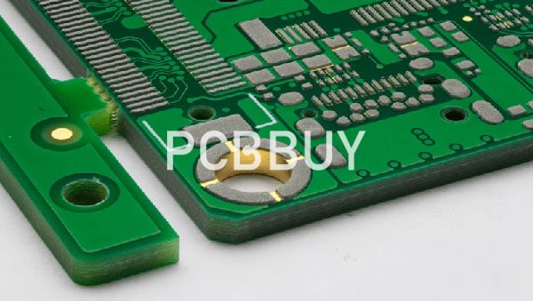
PCBBUY supports first-order and second-order HDI structures. The appropriate structure should be selected according to routing requirements and manufacturability rather than using additional buildup layers simply because the technology is available.
6. How Do Stackup and Material Selection Affect Microvia Yield?
Microvia performance cannot be separated from the dielectric material and stackup.
The dielectric thickness determines the laser-drilling depth and therefore influences the microvia aspect ratio. Material characteristics also affect laser ablation behavior, lamination movement, and thermal expansion.
For HDI designs, engineers should evaluate:
-
Dielectric thickness after lamination
-
Resin content
-
Material compatibility
-
Z-axis thermal expansion
-
Laser-drilling behavior
-
Lamination sequence
-
Registration requirements
A well-designed stackup provides a more predictable manufacturing window.
If the design combines high-frequency materials, different resin systems, or heterogeneous materials, the lamination process becomes more complex. PCBBUY supports asymmetric and heterogeneous mixed-material lamination, but the actual material combination and buildup sequence still need engineering review before production.

7. Which Manufacturing Factors Have the Greatest Influence on Microvia Yield?
Microvia yield is usually the result of multiple process variables working together rather than one isolated parameter.
|
Process Area |
Typical Risk |
Yield-Improvement Approach |
|
Laser drilling |
Irregular profile, incomplete dielectric removal, target-pad damage |
Match laser process to material and dielectric thickness |
|
Desmear |
Residue or inconsistent surface preparation |
Establish appropriate cleaning and activation process |
|
Registration |
Microvia partially misses target pad |
Maintain sufficient pad and alignment margin |
|
Copper plating |
Uneven deposition or weak interfaces |
Control plating conditions according to via structure |
|
Via filling |
Voids or insufficient fill |
Define filling requirements where stacked or via-in-pad structures are used |
|
Lamination |
Layer movement or dimensional variation |
Optimize stackup and sequential lamination process |
|
Inspection |
Latent defects not detected |
Combine visual, dimensional, electrical, and appropriate cross-sectional verification |
The important principle is that yield improvement should start before production. If a microvia design has almost no process margin, improving downstream inspection will identify more defective boards but will not fundamentally improve the process capability.
8. How Can PCBBUY Support Microvia Yield Improvement?
PCBBUY's HDI manufacturing capabilities provide several process options for dense PCB structures.
Its HDI capability includes first-order and second-order structures, with laser blind vias down to approximately Φ0.075 mm and mechanical blind vias down to approximately Φ0.15 mm.
For complex boards, PCBBUY also supports multilayer fabrication and customized high-layer-count PCB structures. This is useful when microvia routing needs to be integrated with high-density BGA escape routing, power distribution, or high-speed signal layers.
For high-current products, PCBBUY supports heavy and partial-heavy copper structures, with stated capabilities of up to 15 oz on outer layers and 8 oz on inner layers, subject to the specific board design and manufacturing process.
Quality control also includes AOI, flying-probe testing, and four-wire low-resistance testing. These methods address different aspects of PCB fabrication and electrical verification.
For microvia-intensive designs, however, the most effective manufacturing approach is to review the Gerber data, stackup, material specification, microvia structure, via diameter, target-pad dimensions, and special fabrication requirements before production.
This is especially valuable for PCBBUY's target application areas, including automotive electronics, industrial control, power and electrical equipment, power supply, energy storage, new-energy products, and embodied robotics.

9. How Should Engineers Design for Better Microvia Yield?
A few practical principles can significantly improve the manufacturing margin.
Avoid Minimum Geometry Without a Clear Need
A manufacturer may support a 0.075 mm laser blind via, but that does not mean every HDI board should use 0.075 mm vias. If a larger via can satisfy the electrical and routing requirements, it may provide a wider manufacturing window.
Keep Microvia Structures Simple Where Possible
Staggered or single-level structures can sometimes be easier to manufacture than more complicated stacked structures. Stacked microvias can be necessary for routing density, but they introduce additional interfaces and process requirements that should be carefully reviewed.
Design the Stackup With the Fabricator
Do not finalize dielectric thickness and microvia dimensions independently. The via depth, diameter, target-pad size, and lamination structure should be evaluated together.
Provide Complete Manufacturing Documentation
Gerber files alone may not communicate the intended microvia construction. The fabrication package should clearly define:
-
Layer stackup
-
Material system
-
Microvia dimensions
-
Blind/buried via structure
-
Via filling requirements
-
Surface finish
-
Copper thickness
-
Special registration requirements
This allows the PCB manufacturer to identify potential conflicts before production rather than discovering them after the first fabrication lot.
Conclusion
Effective microvia yield improvement in HDI PCB manufacturing is not achieved by focusing on laser-drilling accuracy alone. Reliable yield depends on the complete chain of material selection, stackup design, laser drilling, desmear, registration, metallization, via filling, lamination, and inspection.
The most important manufacturing principle is to maintain sufficient process margin. A microvia that is technically possible but designed too close to the process limit may create unnecessary production risk.
PCBBUY's first-order and second-order HDI capabilities, laser blind vias down to approximately Φ0.075 mm, multilayer manufacturing, mixed-material lamination, heavy-copper processing, and electrical inspection capabilities provide a foundation for demanding HDI applications.
The final microvia structure should nevertheless be reviewed against the actual board stackup and production requirements rather than relying solely on the nominal minimum capability.
For automotive, industrial control, power, energy storage, new-energy, and embodied-robotics products, this design-for-manufacturing approach helps turn HDI miniaturization into a repeatable production process rather than simply a smaller PCB geometry.
FAQ
1. What is the biggest factor affecting microvia yield in HDI PCBs?
There is no single universal factor. Laser drilling, target-pad condition, desmear, registration, copper plating, filling, lamination, and material selection can all influence yield. In practice, the interaction between these processes is often more important than one isolated parameter.
2. Does using a smaller microvia automatically reduce PCB yield?
Not necessarily, but smaller geometries generally provide less process margin. A microvia should be made as small as the electrical and routing requirements require, rather than simply using the minimum manufacturing capability.
3. Why can a microvia pass electrical testing but later fail?
Initial electrical continuity does not necessarily reveal latent mechanical or interfacial weaknesses. Thermal and mechanical stresses during assembly and service can cause cracks or separation at vulnerable copper interfaces.
4. What is the purpose of desmear in HDI manufacturing?
Desmear removes residues generated during drilling and prepares the dielectric and target-pad surfaces for subsequent metallization. Inadequate surface preparation can compromise copper adhesion and microvia reliability.
5. What is PCBBUY's minimum laser blind-via capability?
PCBBUY's stated capability supports laser blind vias down to approximately Φ0.075 mm. The actual recommended diameter depends on the dielectric thickness, stackup, target-pad geometry, routing requirements, and overall manufacturing process.
6. How can I improve microvia yield before sending a PCB to production?
The most effective step is an early DFM review. Provide the manufacturer with the complete Gerber package, stackup, material information, microvia dimensions, target-pad requirements, via-filling specifications, copper thickness, and any special HDI requirements. This allows the manufacturer to identify process-margin issues before fabrication.
Industry Category








