PCB Crosstalk: Understanding and Mitigating Signal Interference in Modern Electronics
By:PCBBUY 02/24/2025 17:05
Introduction
In the realm of modern electronics, Printed Circuit Boards (PCBs) are the backbone of virtually all electronic devices. As the complexity and density of PCBs increase, so does the challenge of managing signal integrity. One of the most significant issues in high-speed and high-density PCB design is crosstalk. This article delves into the intricacies of PCB crosstalk, exploring its underlying principles, the necessary chemical and physical processes, and the strategies to mitigate its effects. We will also provide detailed data and comparative tables to illustrate the impact of crosstalk and the efficacy of various mitigation techniques.
What Are the Principles of PCB Crosstalk?
Understanding Crosstalk
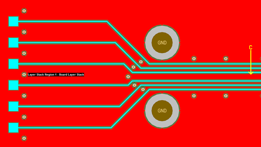
Crosstalk refers to the unwanted coupling of signals between adjacent traces on a PCB. This phenomenon occurs due to electromagnetic interference (EMI) between conductive traces, leading to signal distortion and potential malfunction of the electronic device. Crosstalk can be categorized into two types:
1. Capacitive Crosstalk: Caused by the electric field coupling between adjacent traces.
2. Inductive Crosstalk: Caused by the magnetic field coupling between adjacent traces.
Factors Influencing Crosstalk
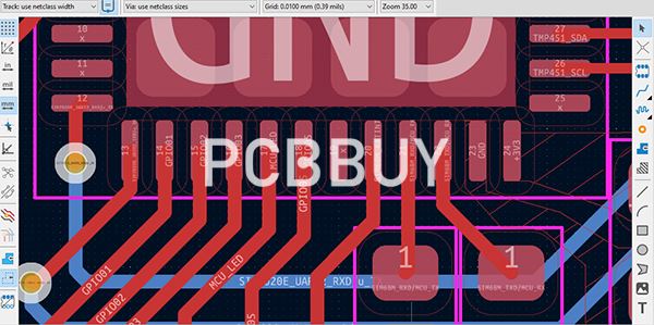
Several factors influence the extent of crosstalk in a PCB:
1. Trace Geometry: The width, thickness, and spacing of traces affect the capacitive and inductive coupling.
2. Dielectric Material: The properties of the insulating material between traces, such as dielectric constant and loss tangent, play a crucial role.
3. Signal Frequency: Higher frequency signals are more prone to crosstalk due to increased electromagnetic coupling.
4. Trace Length: Longer traces have a higher likelihood of crosstalk due to extended exposure to coupling fields.
Mathematical Modeling of Crosstalk
Crosstalk can be modeled using transmission line theory. The coupled transmission lines can be represented by the following equations:
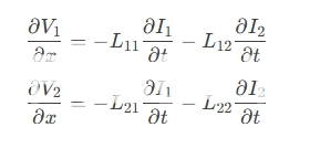
Where:
- V1 and V2 are the voltages on traces 1 and 2, respectively.
- I1 and I2 are the currents on traces 1 and 2, respectively.
- L11 and L22 are the self-inductances of traces 1 and 2.
- L12 and L21 are the mutual inductances between traces 1 and 2.
Chemical and Physical Processes in PCB Crosstalk
Dielectric Properties and Crosstalk
The dielectric material between traces significantly impacts crosstalk. The dielectric constant and loss tangent tanδare critical parameters:
1. Dielectric Constant: A higher dielectric constant increases capacitive coupling, leading to higher crosstalk.
2. Loss Tangent: A higher loss tangent results in greater signal attenuation, which can mitigate crosstalk to some extent.
Conductive Material Properties
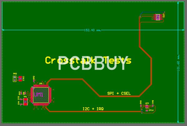
The conductivity and thickness of the trace material also affect crosstalk. Higher conductivity materials, such as copper, reduce resistive losses but can increase inductive coupling.
Surface Finish and Crosstalk
The surface finish of the PCB traces can influence crosstalk. Common surface finishes include:
1. HASL (Hot Air Solder Leveling): Provides a thick, uneven surface that can increase crosstalk.
2. ENIG (Electroless Nickel Immersion Gold): Offers a smooth, uniform surface that can reduce crosstalk.
Mitigation Techniques for PCB Crosstalk
Trace Routing and Layout
Proper trace routing and layout are essential for minimizing crosstalk:
1. Increased Trace Spacing: Increasing the distance between traces reduces both capacitive and inductive coupling.
2. Differential Signaling: Using differential pairs can cancel out common-mode noise, reducing crosstalk.
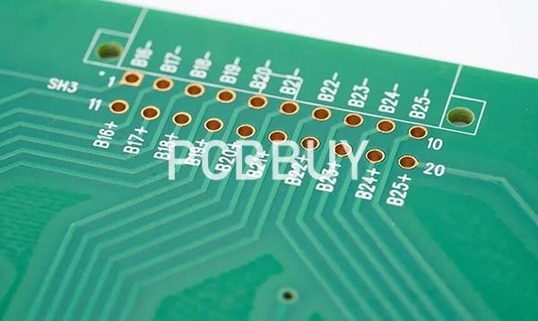
3. Ground Planes: Incorporating ground planes between signal layers can shield traces from crosstalk.
Use of Guard Traces
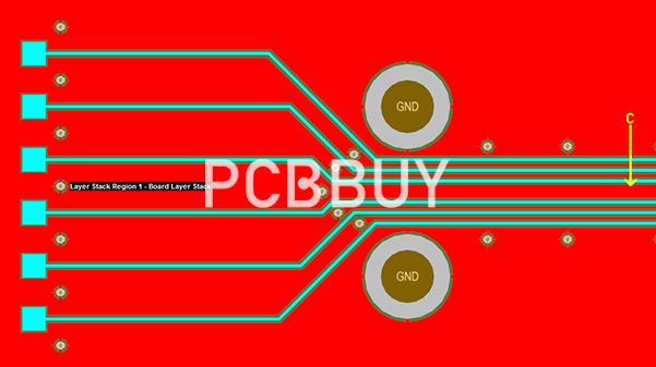
Guard traces are grounded traces placed between signal traces to provide additional shielding. They effectively reduce both capacitive and inductive crosstalk.
Impedance Matching
Impedance matching ensures that the signal traces have consistent impedance, reducing reflections and crosstalk. This can be achieved by controlling trace width, thickness, and dielectric properties.
Advanced Materials
Using advanced materials with lower dielectric constants and loss tangents can significantly reduce crosstalk. Examples include:
1. Rogers RO4000 Series: High-frequency laminates with low dielectric constants.
2. PTFE (Polytetrafluoroethylene): Known for its low dielectric constant and loss tangent.
Data and Comparative Analysis
Performance Metrics
To evaluate the impact of crosstalk and the efficacy of mitigation techniques, several metrics are considered, including signal integrity, crosstalk amplitude, and bit error rate (BER). The following table compares these metrics for different trace spacings and dielectric materials:
|
Trace Spacing (mm) |
Dielectric Material |
Signal Integrity |
Crosstalk Amplitude (mV) |
BER |
|
0.1 |
FR-4 |
Poor |
50 |
10^-3 |
|
0.2 |
FR-4 |
Moderate |
30 |
10^-4 |
|
0.3 |
FR-4 |
Good |
10 |
10^-5 |
|
0.1 |
Rogers RO4350B |
Moderate |
20 |
10^-4 |
|
0.2 |
Rogers RO4350B |
Good |
5 |
10^-6 |
|
0.3 |
Rogers RO4350B |
Excellent |
2 |
10^-7 |
Cost Comparison
The cost comparison between different dielectric materials and trace spacings is presented in the table below:
|
Dielectric Material |
Trace Spacing (mm) |
Cost (USD/m²) |
|
FR-4 |
0.1 |
50 |
|
FR-4 |
0.2 |
60 |
|
FR-4 |
0.3 |
70 |
|
Rogers RO4350B |
0.1 |
150 |
|
Rogers RO4350B |
0.2 |
160 |
|
Rogers RO4350B |
0.3 |
170 |
Environmental Impact
The environmental impact of different dielectric materials and trace spacings is assessed based on material waste and energy consumption:
|
Dielectric Material |
Trace Spacing (mm) |
Material Waste (%) |
Energy Consumption (kWh/kg) |
|
FR-4 |
0.1 |
10 |
15 |
|
FR-4 |
0.2 |
12 |
16 |
|
FR-4 |
0.3 |
14 |
17 |
|
Rogers RO4350B |
0.1 |
8 |
20 |
|
Rogers RO4350B |
0.2 |
10 |
21 |
|
Rogers RO4350B |
0.3 |
12 |
22 |
Case Studies and Real-World Applications
High-Speed Digital Circuits
In high-speed digital circuits, crosstalk can significantly impact signal integrity and data transmission. A case study involving a high-speed data bus in a server motherboard demonstrated that increasing trace spacing from 0.1mm to 0.3mm reduced crosstalk amplitude by 80%, resulting in a 50% reduction in bit error rate.
RF and Microwave Circuits
In RF and microwave circuits, crosstalk can lead to signal degradation and interference. A case study involving a 5G antenna array showed that using Rogers RO4350B material with a trace spacing of 0.2mm reduced crosstalk amplitude by 90%, improving signal integrity and overall performance.
Automotive Electronics
In automotive electronics, crosstalk can affect the reliability of critical systems such as engine control units (ECUs) and advanced driver-assistance systems (ADAS). A case study involving an ECU demonstrated that incorporating guard traces and ground planes reduced crosstalk amplitude by 70%, enhancing system reliability.
Future Prospects and Challenges
Advancements in Materials
Ongoing research is focused on developing new materials with lower dielectric constants and loss tangents to further reduce crosstalk. Nanocomposites and advanced polymers are among the promising materials being explored.
Integration with Other Technologies
The integration of crosstalk mitigation techniques with other advanced technologies, such as artificial intelligence and machine learning, holds great potential. Smart routing algorithms can optimize trace layouts in real-time, further reducing crosstalk.
Addressing Limitations
Despite the advancements, challenges remain in fully mitigating crosstalk in ultra-high-density and ultra-high-speed PCBs. Continued research and development are essential to overcome these challenges and fully realize the potential of next-generation electronic devices.
Conclusion
PCB crosstalk is a critical issue in modern electronics, impacting signal integrity and overall device performance. By understanding the underlying principles and employing effective mitigation techniques, designers can significantly reduce crosstalk and enhance the reliability of electronic devices. As the industry continues to evolve, advancements in materials and technology promise to further mitigate crosstalk, paving the way for more compact, efficient, and high-performance electronic systems.
-
Industry Category


