PCB Mechanical Stress
By:PCBBUY 08/27/2021 09:24

During the PCB manufacturing, there might be mechanical stress on the board. But, do you know what PCB mechanical stress is? Mechanical stress is the internal force that interacts with each part of an object when it is deformed due to an external cause (force, load, temperature, etc.) to resist the effect of this external cause, and tries to make the object from the deformed position. Revert to the position before the deformation.
In this passage, we will tell you everything about PCB mechanical stress. Check and read the content below to learn how to overcome PCB mechanical stress.

What are the main types of PCB mechanical stress?
The mechanical stress in the assembly manufacturing process mainly includes the following aspects:
· The force acting on PCBA during the operation of tooling equipment.
· The rapid difference between the cold and hot changes in the welding process on the PCBA force.
· Tolerance to mechanical shock by collision and fall when PCBA board is taken improperly
· PCBA packaging improper protection, tolerance to vibration in the transport process.
How to reduce PCB mechanical stress?
Obviously, PCB mechanical stress can be a significant problem during manufacturing. Therefore, it is imperative that you employ DFM guidelines and principles established by and acquired from the CM that will build your boards. Included should be DFA rules specifically targeted to the PCB assembly process. To optimize your PCB mechanical stress avoidance strategy, it is a good idea to incorporate the following guidelines, as well.
Guidelines for Overcoming PCB Mechanical Stress Issues during Manufacturing
· Avoid using moisture-sensitive components.
· Do not push the boundaries of your CM’s equipment capabilities, as this may result in lower than desired yield rates.
· Consider increasing board edge clearance when delicate components; such as tall electrolytic caps and glass body ICs, are used.
· Attempt to design boards with the standard PCB thickness of ≅ 62 mil or 1.6 mm and ensure that thinner boards include mechanical support of fixtures during manufacturing.
· Strive for symmetry in your PCB stackup design.
· Design for the minimum number of lamination cycles to prevent board failures during manufacturing or degradation that may result in a shortened lifecycle.
· Make sure your fabricator uses quality materials with adequate resin venting and employs adequate wet-out.
· Make sure your fabricator has a quality, consistent drilling process, including desmear procedure.
· Opt for a PCB surface finish other than OSP, which is far easier to damage than other types.
· Make sure your assembler employs good cleaning techniques.
· Work with or allow your CM to define PCB panelization strategy.
· Make sure to observe proper handling and storage protocols throughout manufacturing.
· Ensure that adequate PCB inspection methods are utilized.

What is the analysis of PCB mechanical stress?
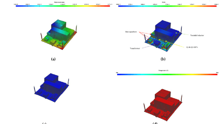
Structural and thermal integrity are critical design considerations for packages/PCBs that affect reliability and structural integrity. Thermal impact on the package, especially from the IC, is a key driver for material selection, cooling, and form factor decisions, that ultimately determine the size, weight and cost of the final product. It is critical for package and system designers to determine the thermal signature of their system. ANSYS delivers an automated design flow that streamlines EM-thermal coupled analysis and links to mechanical analysis to predict the structural impact on the electronic package.
ANSYS Icepak performs heat transfer and fluid flow simulation enabling engineers to analyze transient steady-state thermal conditions and develop effective cooling strategies for all types of electronic applications including wearables and data centers. Unique to ANSYS is that we provide a comprehensive, integrated electrical-thermal-mechanical simulation solution. PCB problems can be broadly classified as electrical, thermal and mechanical. Power distribution problems include signal integrity, crosstalk and electromagnetic interference. Current flow in a PCB and through the electronic components causes power losses across the board and leads to power dissipation in the components, mainly the ICs. Power losses in conductors within the board and heat generated by ICs increase their temperatures, leading to thermal problems. Moreover, modern microprocessors can demand peak currents of 100 amperes or more. These high currents cause significant heat dissipation in the ICs and significant Joule or Ohmic heating in the connected power planes and traces.
![]()
Even a small change in temperature can affect a device’s performance due to the inverse relationship between electrical and thermal conductivities. Temperature gradients across the board and components can produce mechanical reliability problems due to the cyclic nature of thermal transients. This follows from the principle of the bimetallic strip, which can convert temperature differences into mechanical displacement. Per this principle, when two metals with dissimilar thermal expansion coefficients are bonded together, they will bend if they are heated. This bending can cause solder joints to crack or even result in delamination of the board or traces on the PCB. With the ANSYS design flow you can perform DC analysis, calculate Joule heating then produce temperature profiles and associated mechanical deformation and stress. It’s a chip - package – PCB quote solution that allows engineers to evaluate electrical, thermal, and structural behavior.
Industry Category


