PCB Thermal Cycling Test
By:PCBBUY 09/03/2021 10:28

Thermal cycling resistance is not a specific physical property that can be measured. Instead, it’s simply a quality of an electronic device referring to its ability to withstand thermal cycling. Thermal cycling is simply the thermal analog of vibration—repeated mechanical stress is exerted on structures in the PCB leading to fatigue and failure.
Components have their absolute maximum temperature ratings that need to be adhered to, but repeated thermal cycling can cause failures in two PCB structures: solder and vias. In this passage, you can get everything about PCB thermal cycling, come and check the content we provide below.
What is the Importance of PCB thermal management?
Current silicon-based components have a junction temperature between about 125°C and 200°C. However, it is necessary to avoid reaching this value, otherwise the residual life of the component will deteriorate rapidly. In fact, it is estimated that an increase in operating temperature of 20°C, due to inefficient thermal management, can reduce component life by up to 50%. High brightness LEDs, for instance, convert over 60% of the absorbed power into heat and therefore require special printed circuit boards capable of handling high temperatures without damaging the components.
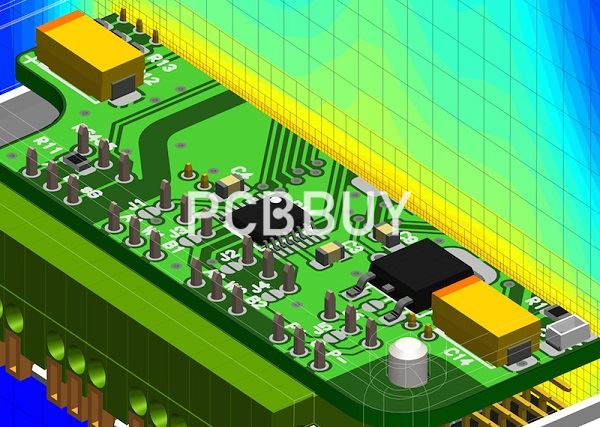
The growing popularity of wide bandgap (WBG) semiconductors, such as gallium arsenide (GaN) and silicon carbide (SiC), has allowed components to reach higher operating temperatures than silicon-based technology. This, however, has not eliminated the need for accurate thermal management, capable of evenly distribute the generated heat, avoid the formation of dangerous heat accumulation points (hot spots) and minimizing power losses. Figure 1 shows an electronic circuit subjected to thermal scanning by infrared camera: the red colored parts correspond to the points of greatest heat concentration.
What are the main methods of PCB thermal cycling?
Identifying thermal hotspots and high-current traces
To fabricate a thermally stable PCB, thermal effects must be studied during the designing phase itself. The first step in thermal design is to identify the hotspots. Thermal modeling or thermal simulation techniques are used to find hotspots. Also, current flow analysis must be done along with it, because high-current traces cause heat generation.

The proper geometrical arrangement of components and high-current traces enables even distribution of heat. High-current traces must be routed away from thermally sensitive components such as sensors and Op-amps.
Copper thickness and width of traces
The thickness and width of the copper pad or traces play a significant role in PCB thermal design. Copper trace thickness should be adequate to provide a low impedance path for current passing through it. This is because the resistance of copper traces and vias accounts for significant power loss and heat generation particularly when they bear high current density. Therefore sufficient trace width and thickness are recommended to reduce heat generation.
Placing of high power components in PCB
For better heat dissipation, high power components such as processors and microcontrollers should be placed at the center of the PCB. If a high power component is mounted near to the edge of the board, it will accumulate heat at the edge and raise the local temperature. But if the device is placed at the center of the board, heat will scatter over the surface in all directions. Thus the surface temperature of the PCB would be lower and dissipates easily.
Also, make sure you have placed high-power components away from sensitive devices and keep the proper spacing between two high-power devices. Try to place high-power components evenly across the PCB quote.
How to analyze PCB thermal?
Since thermal expansion is so important in any PCB that will be repeatedly thermally cycled, you’ll need to determine by how much conductors in your board will expand during cycling. As a board is brought to a high temperature, the substrate and conductors expand, but they can expand at different rates. FR4 substrates experience greater expansion than copper, which puts stress on conductors. Traces on a board are less susceptible to failure as they are sufficiently thick.

In FR4, the thermal expansion coefficient (CTE) increases once the board’s temperature rises above the glass transition temperature. It is always best to use a high-Tg laminate if your board will run at a high temperature as you want to stay below the glass transition temperature.
Simulating microcrack accumulation during repeated thermal cycling is not a simple problem, and simulating this directly is a complex random-walk problem in a random system. However, In general, when the difference between the extreme temperatures is smaller, the board can withstand more cycles.
The thermomechanical analysis process for electronics proceeds in the following order:
· Steady-state temperature calculation: Calculate the steady-state temperature while a board is in operation. This should include the operation of all cooling fans and components.
· Convert temperature rise to volume expansion: Once the temperature in each region of a board is calculated, it can be converted to a volume change using a CTE value.
· Calculate strain on various structures due to expansion: The strain experienced by different structures in the board is equal to the volume expansion. For a via, which gets mechanically stressed under expansion, the via experiences some additional mechanical strain.
The best tool for calculating the steady-state temperature distribution is to use a thermal CFD simulator that builds an FEA/FDTD mesh directly from your design data. The temperature change you calculate in the system is then multiplied by the CTE value, which determines the thermal strain. To the total strain on conductors, you need to consider the exact structure being strained during expansion.
Industry Category


