Top 5 Main Aspects of Automotive PCB Design Guidelines for Beginners
By:PCBBUY 11/11/2021 09:51

As discussed above, there are distinct challenges in designing boards for use in AVs and EVs. Fortunately, there is a set of automotive PCB design guidelines that, if followed, will go a long way toward ensuring your board development will yield high-quality, reliable PCBAs. Designing PCBAs for advanced automotive systems is better for PCB manufacturing.
If you are going to learn more about automotive PCB design guidelines, please check and read more professional information. If you are curious about the details about automotive PCB design guidelines, welcome to read the content below.

1. What is the basic definition of automotive PCB design?
To achieve the smart operational requirements of advanced automotive systems necessitates following specific essential automotive PCB design guidelines. These guidelines can be best understood by first exploring the challenges of designing boards for these vehicles. In this article, we will focus the features of automotive PCB, please check the content we prepare to learn more information about it.
2. What are the types of automotive PCB design?
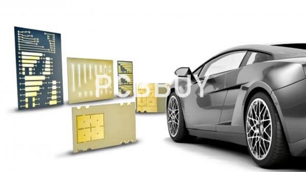
In order to meet the stringent requirements of space, weight and cost, automotive industry uses different types of PCBs that differ from each other both in the structure and in the type of material or substrate used. The main types of PCBs for automotive applications are as follows:
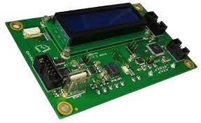
· Rigid PCBs: these are the traditional PCBs, not flexible and normally manufactured using FR4. Applications includes display monitors and reverse cam screens;
· Flex PCBs: these printed circuit boards are built with flexible plastic substrates and use of materials such as polyamide, polyetheretherketone (peek) or transparent polyester films. The advantage of these boards is that they can be twisted and bent. Applications are numerous, especially where space is limited or irregular in shape, and include the connection of displays, control panels and light switches;
· Rigid-flex PCBs: they are a combination of the two types of PCBs mentioned above and therefore offer the advantages of both. Rigid-flex PCBs are used, for instance, in lighting systems;
· LED PCBs: the increasingly massive use of high power and high brightness LEDs requires PCBs with excellent heat dissipation, typically made with a metal substrate such as aluminum. PCBs of this type are used in car indicators, headlights, and brake lights;
· HDI PCBs: HDI, acronym for High Density Interconnect, indicates printed circuit boards with high density of electrical connections per unit of area. These PCBs have finer spaces and lines, minor vias and capture pads and higher connection pad density. Widely used in infotainment systems, HDI PCBs help improve the quality of wiring, reducing the weight and size of the solution.
3. What are the multiple categories of automotive PCBs?
Automobiles combine machinery and electronic equipment. Modern automobile technology integrates traditional technique and advancing scientific technology, such as manual inner decorating parts and advancing GPS. In modern automobiles, there is electronic equipment with different functions at different positions and different functions derive from different types of PCBs.

According to substrate materials, automotive PCBs can be classified into two main categories: inorganic ceramic-based PCB and organic resin-based PCB. Ceramic-based PCB features high temperature resistance and excellent size stability, making it directly applied in motor system with high temperature. However, it features bad ceramic manufacturability and high cost. At present, with the development of resin substrate material in terms of its heat resistance capability, resin-based PCB has been widely applied in automobiles with substrate material with different performances applied in different positions.
Generally speaking, Flexible PCBs and Rigid PCBs are applied in normal gauges indicating vehicle speed and mileage and air conditioner equipment. Double-layer or multi-layer PCBs and Flex PCBs are used in audio and video entertainment equipment inside automobiles. For communication and wireless positioning equipment and security control equipment, multi-layer PCBs, HDI printed circuit boards and Flex PCBs are applied.
4. How to assure the quality of automotive PCBs?
A basic demand of long-term quality assurance for manufacturers or distributors lies in a sound quality management system, that is, ISO9001 from international perspective. Owing to particularity of automotive industry, three leading automotive manufacturers from North America co-established a quality management system in 1994 uniquely for automotive industry, that is, QS9000. At the beginning of 21st century, a new quality administration system was published by world automotive manufacturers based on regulations of ISO9001, that is, ISO/TS16949.
As technical regulations for automotive industry around the globe, ISO/TS16949 integrates special requirement for automotive industry and focuses on defects prevention, quality fluctuation and waste reduction in the supply chain of automotive components.
5. How to balance the grounding of automotive PCBs?
Grounding or power plane defines a public reference voltage that supplies power to all components in the system through low impedance path. Based on that scheme, all the electric fields can be balanced with excellent shielding scheme generated.

Direct current always flows through low impedance path. Similarly, high-frequency current is also a path flowing through the lowest impedance at the first minute. Therefore, for standard PCB leads above ground plane, return current tries to flow into the grounding area rightly under leads. Afterwards, split grounding area arouses all kinds of noises, which further increases crosstalk through magnetic field coupling or current accumulation. As a result, ground integrity should be ensured as much as possible, or return current will drive crosstalk.
In addition, filling ground, also called protective wire, is usually applied for design of circuits containing areas where continuous ground is difficult to be arranged or that requires shielding sensitive circuits. Grounding thru holes can be positioned at terminals of wires or along the wires to increase shielding effect. Protective wires can't be mixed with leads designed to provide return current path, which will bring forward crosstalk.
Industry Category


