What Are Factors Affecting PCB Thickness Tolerance?
By:PCBBUY 04/27/2025 15:35

Printed Circuit Boards (PCBs) are fundamental components in modern electronics, offering a platform for electrical connections and mechanical support. One of the critical aspects of PCB design and manufacturing is thickness tolerance. Thickness tolerance impacts various aspects of PCB functionality, including impedance control, mechanical stability, and thermal performance. This article delves into the essential tips for managing PCB thickness tolerance, providing insights into industry standards, best practices, and the implications of different materials and design choices.
1. Introduction to PCB Thickness Tolerance
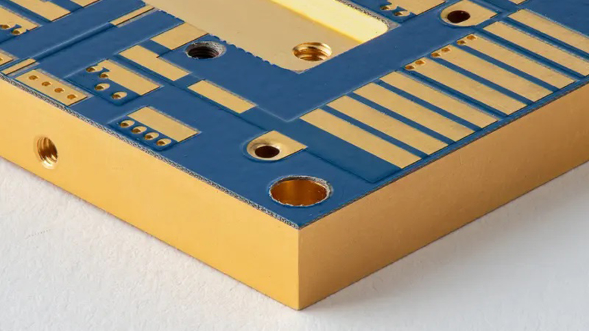
PCB thickness tolerance refers to the permissible deviation in the thickness of a PCB from its specified design thickness. Maintaining accurate thickness tolerance is crucial for the board's reliability, signal integrity, and mechanical fit. Standard PCB thickness typically ranges from 0.4mm to 3.2mm, but the exact tolerance level depends on the board's application, materials, and manufacturing processes.
-
Definition: Thickness tolerance in PCBs is the allowable deviation from the nominal thickness, which can impact electrical performance and assembly compatibility.
-
Importance: Correct thickness tolerance ensures compatibility with connectors, enclosures, and other components, while also influencing the board's thermal and mechanical properties.

2. Factors Affecting PCB Thickness Tolerance
Several factors can influence PCB thickness tolerance, including:
-
Material Selection: Different substrate materials have varying thickness tolerances due to their physical properties. For example, FR4 has different tolerances compared to Rogers materials.
-
Copper Weight: The amount of copper used in the layers impacts the overall thickness and can cause variations if not controlled properly.
-
Lamination Process: The number of layers and the lamination process can lead to variations in thickness due to the flow and cure of prepreg materials.
-
Manufacturing Process Control: Precision in the manufacturing process, including pressing, drilling, and etching, plays a significant role in maintaining thickness tolerance.
3. Industry Standards for PCB Thickness Tolerance
Understanding industry standards helps designers set realistic expectations for thickness tolerance.
-
IPC-6012: This standard specifies the performance and acceptance criteria for rigid PCBs, including thickness tolerance. It defines acceptable levels for different classes of PCBs.
-
Class 1: General electronic products (e.g., consumer electronics).
-
Class 2: Dedicated service electronic products (e.g., communication equipment).
-
Class 3: High reliability or harsh environment electronic products (e.g., aerospace and medical devices).
-
Typical Tolerances:
-
For PCBs up to 1.57mm thick, the tolerance is usually ±10% of the board thickness.
-
For boards thicker than 1.57mm, the tolerance can be ±0.15mm or tighter depending on the application requirements.

4. Material Choices and Their Impact on Thickness Tolerance
Different materials have inherent properties that affect their thickness tolerance.
-
FR4: A commonly used fiberglass-reinforced epoxy laminate, offers good thickness stability and is cost-effective. Typical tolerance is ±10% of the nominal thickness.
-
Rogers Materials: Used for high-frequency applications, these materials may have tighter thickness tolerances to meet impedance control requirements.
-
Flexible PCBs: They use polyimide films, and thickness tolerance is critical to maintain flexibility and ensure reliable bending without damaging the circuit.
5. Design Considerations for Thickness Tolerance
When designing a PCB, considering thickness tolerance is crucial for both performance and manufacturability.
-
Impedance Control: Accurate thickness tolerance is essential for maintaining controlled impedance in high-frequency signal traces. Even slight deviations can lead to impedance mismatches, causing signal reflections and losses.
-
Thermal Management: Thickness variations can affect the thermal conductivity of the PCB. Ensuring uniform thickness helps in effective heat dissipation, which is crucial for high-power applications.
-
Mechanical Stability: PCBs with tighter thickness tolerance offer better mechanical stability, reducing the risk of warping and ensuring that the board fits properly into enclosures and connectors.

6. Manufacturing Techniques to Control PCB Thickness Tolerance
To maintain PCB thickness within specified tolerance limits, several manufacturing techniques are employed:
-
Precision Lamination: Using advanced lamination processes that control the flow of prepreg materials can help maintain uniform thickness across the board.
-
CNC Drilling and Routing: Precision drilling and routing machines ensure that the board thickness remains consistent at drilled holes and edges.
-
Planarization Techniques: Planarization, or flattening processes, such as buffing and sanding, can be used to achieve uniform thickness after copper plating and lamination.
7. Measuring and Verifying PCB Thickness
Accurate measurement of PCB thickness is crucial during the manufacturing process. Several methods are commonly used:
-
Mechanical Micrometers: Simple and effective for measuring the overall thickness of the PCB stack.
-
Laser Thickness Gauges: Provide non-contact measurement with high precision, suitable for continuous monitoring during production.
-
X-ray Fluorescence (XRF) Analysis: Used for measuring copper layer thickness and ensuring consistent metal distribution.

8. Challenges in Maintaining PCB Thickness Tolerance
Maintaining consistent PCB thickness tolerance can be challenging due to:
-
Material Variability: Variations in material thickness can occur due to differences in supplier batches or production runs.
-
Environmental Factors: Temperature and humidity variations during manufacturing can cause expansion or contraction of materials.
-
Process Variability: Differences in lamination pressure, temperature, and time can lead to thickness variations.
9. Tips for Designers to Manage Thickness Tolerance
Designers can follow these tips to manage PCB thickness tolerance effectively:
-
Specify Clear Requirements: Clearly define thickness tolerance requirements in the design specifications and communicate them to the manufacturer.
-
Select Suitable Materials: Choose materials with known and consistent thickness tolerance properties to minimize variability.
-
Work with Reputable Manufacturers: Partner with PCB manufacturers that have robust process controls and quality assurance measures in place.
-
Design for Manufacturability (DFM): Incorporate design features that accommodate slight variations in thickness, such as adjustable connector heights or flexible mounting options.

10. Conclusion
PCB thickness tolerance is a critical factor that influences the overall performance, reliability, and manufacturability of electronic products. By understanding the factors that affect thickness tolerance, adhering to industry standards, and employing best practices, designers and manufacturers can ensure that PCBs meet the desired specifications. This not only enhances the product's quality but also contributes to the longevity and efficiency of the end application.
References
-
IPC-6012, “Qualification and Performance Specification for Rigid Printed Boards,” IPC, 2015.
-
Johnson, H. W., & Graham, M., “High-Speed Digital Design: A Handbook of Black Magic,” Prentice Hall, 1993.
-
Goyal, R., “Practical RF PCB Design,”Artech House, 2006.
-
Ulrich, K. T., & Eppinger, S. D., “Product Design and Development,” McGraw-Hill Education, 2015.
-
Rogers Corporation, “PCB Laminate Materials for High-Frequency Applications,” Rogers Corporation, 2020.
Industry Category


