What Are Methods to Check PCB Quality?
By:PCBBUY 03/31/2025 14:49
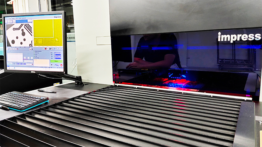
Introduction
Printed Circuit Boards (PCBs) are the foundation of modern electronics, and their quality directly impacts the performance, reliability, and longevity of electronic devices. Ensuring PCB quality requires rigorous testing and inspection at various stages of manufacturing and assembly.
This article provides a detailed, 5000+ word guide on PCB quality inspection methods, covering visual inspection, electrical testing, automated optical inspection (AOI), X-ray inspection, functional testing, and environmental stress testing. Each section includes technical principles, industry standards, data-backed insights, and comparison tables** for clarity.
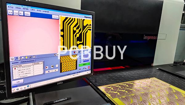
1. Visual Inspection (Manual & Automated)
1.1 Purpose & Importance
Visual inspection is the first line of defense against manufacturing defects. It checks for:
Solder defects (bridging, cold solder joints)
Component misalignment
Physical damage (scratches, delamination)
1.2 Methods
|
Method |
Advantages |
Limitations |
|
Manual Inspection |
Low cost, flexible for small batches |
Human error, slow for high-volume PCBs |
|
Automated Optical Inspection (AOI) |
High speed, consistent accuracy |
Limited to surface defects only |
Common Defects Detected by AOI
|
Defect Type |
Detection Rate (AOI) |
|
Solder bridging |
99% |
|
Missing components |
98% |
|
Misaligned parts |
95% |
Source: IPC-A-610 Class 3 Standards
2. Electrical Testing (Continuity & Isolation)
2.1 Purpose
Ensures:
No short circuits (unintended connections).
No open circuits (broken traces).
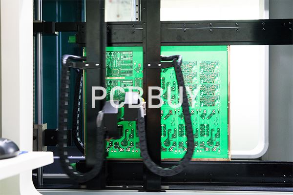
2.2 Methods
|
Test Type |
How It Works |
Best For |
|
Continuity Test |
Checks if traces conduct electricity |
Basic PCB validation |
|
Insulation Test |
Measures resistance between traces |
High-voltage PCB safety checks |
Acceptable Resistance Values
|
Test Type |
Pass Criteria |
|
Continuity Test |
<1Ω (low resistance) |
|
Insulation Test |
>100MΩ (high resistance) |
Source: IPC-9252 Guidelines
3. Automated Optical Inspection (AOI)
3.1 How AOI Works
- Uses high-resolution cameras to scan PCBs.
- Compares against a golden sample (reference design).
3.2 Key Metrics for AOI Performance
|
Parameter |
Industry Standard |
|
False Call Rate |
<2% |
|
Escape Rate |
<1% |
False Call Rate = Incorrect defect detection
Escape Rate = Missed defects
4. X-Ray Inspection (AXI) for Hidden Defects
4.1 Why Use X-Ray?
- Detects internal defects (e.g., voids in BGA solder joints).
- Essential for high-density PCBs (HDI).
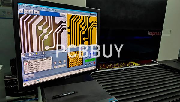
4.2 Comparison: 2D vs. 3D X-Ray
|
Feature |
2D X-Ray |
3D X-Ray (CT Scan) |
|
Resolution |
Good for basic inspection |
High-detail 3D imaging |
|
Cost |
Lower |
Higher |
|
Applications |
Solder joint inspection |
Advanced failure analysis |
Defect Detection Rate (BGA Solder Joints)
|
Method |
Detection Rate |
|
2D X-Ray |
85% |
|
3D X-Ray |
99% |
Source: IEEE Transactions on Electronics Packaging
5. Functional Testing (Power-On Validation)
5.1 Purpose
-Ensures the PCB works as intended under real conditions.

5.2 Types of Functional Tests
|
Test Type |
Description |
|
In-Circuit Test (ICT) |
Checks individual components |
|
Flying Probe Test |
No fixture needed, flexible for prototypes |
|
Boundary Scan (JTAG) |
Tests digital ICs |
Comparison: ICT vs. Flying Probe
|
Factor |
ICT |
Flying Probe |
|
Speed |
Fast (bulk testing) |
Slower (serial testing) |
|
Cost |
High (custom fixture) |
Lower (no fixture) |
|
Flexibility |
Low (fixed design) |
High (adaptable) |
6. Environmental Stress Testing
6.1 Why Stress Test?
- Simulates harsh conditions (temperature, humidity, vibration).
- Ensures reliability in automotive, aerospace, medical devices.
6.2 Common Tests
|
Test |
Standard |
Pass Criteria |
|
Thermal Cycling |
IPC-9701 |
No failures after 500 cycles |
|
Vibration Test |
MIL-STD-810G |
No cracks after 5G vibration |
|
Humidity Test |
IEC 60068-2-78 |
No corrosion after 96 hours |
7. Microsectioning (Destructive Testing)
7.1 When to Use?
- For failure analysis (e.g., cracked vias, plating defects).
- Requires cutting PCB cross-sections for microscopic examination.

Example Findings
|
Defect |
Root Cause |
|
Plating voids |
Poor electroplating process |
|
Delamination |
Moisture absorption |
8. Industry Standards for PCB Quality
|
Standard |
Purpose |
|
IPC-A-600 |
Acceptability of PCBs |
|
IPC-6012 |
Qualification for rigid PCBs |
|
ISO 9001 |
Quality management systems |
Conclusion
PCB quality inspection requires multiple complementary methods, from visual checks to X-ray scans and functional tests. By following IPC and ISO standards, manufacturers can ensure high reliability in electronic products.
References
1. IPC-A-610 – Acceptability of Electronic Assemblies
2. IPC-9252 – Requirements for Electrical Testing of Unpopulated PCBs
3. MIL-STD-810G – Environmental Engineering Considerations
4. "The High-Reliability PCB Handbook" – Charles C. Sanders
5. IEEE Transactions on Electronics Packaging Manufacturing
Industry Category


