Understanding and Preventing Common PCB Component Failures
By:PCBBUY 11/10/2022 17:00
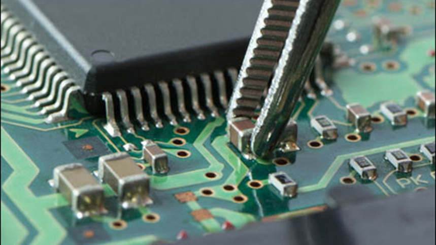
Printed Circuit Boards (PCBs) are the backbone of virtually all electronic devices. Yet even the most well-designed PCB can fail due to component-related issues. In this article, we explore Common PCB Component Failures, why they happen, and how to prevent them through robust inspection, design, and sourcing strategies. This content aims to help PCB designers, PCB manufacturers, and engineers minimize component-related issues and improve product reliability.
What Is a Common PCB Component Failure?
PCB component failure refers to the malfunction or sub-optimal performance of a component mounted on a printed circuit board. These failures can lead to PCB product breakdowns or a decline in performance, potentially rendering devices unusable. According to a 2023 IPC industry report, approximately 28% of PCB failures are due to component issues alone.
Common failure manifestations include:
-
Complete electrical open or short
-
Degraded signal transmission
-
Overheating or thermal runaway
-
Mechanical dislodging of components

Essential Data for Root Cause Analysis of Common PCB Component Failures
To accurately perform a root cause analysis (RCA) of PCB component failures, you need the following:
1. Circuit Board Design Information
-
Board dimensions, layers, and routing
-
Mechanical stresses and vibration loads
-
Heat dissipation and thermal profile
2. Materials and Process Specifications
-
Bill of Materials (BOM) and datasheets
-
Assembly process steps (e.g., solder reflow, cleaning)
-
Storage and handling protocols
3. Manufacturing Process Records
-
Chemical analysis and material certifications
-
Mechanical stress testing results
-
In-circuit test (ICT) and functional test reports
4. Environmental and Operational Conditions
-
Temperature, humidity, and pressure exposure
-
Electrical load variations
-
Location of installation (e.g., indoor, outdoor, aerospace)
5. Maintenance Logs
-
Historical failure records
-
Vibration and shock monitoring logs
-
Preventive maintenance interventions
How to Optimize Component Placement for PCB Reliability
A key factor influencing long-term PCB functionality is component placement strategy. Poor layout and incorrect positioning are leading contributors to common component failures.
1. Component Availability and Lead Time
Hard-to-source or discontinued components can delay production and drive up costs. In 2022, global shortages of MLCCs (multi-layer ceramic capacitors) impacted over 38% of consumer electronics manufacturers.
2. Orientation and Proximity
Incorrect orientation may reduce solder joint reliability. For instance, placing polarized components backwards (e.g., diodes, electrolytic capacitors) can cause immediate short circuits.
3. Heat-Generating Components
Components like voltage regulators and processors should not be placed next to heat-sensitive elements (e.g., crystal oscillators). Simulation using thermal modeling software can reduce hotspots.
4. Mechanical Clearance and Stress Isolation
Mechanical forces during handling or vibration must not transfer stress to solder joints. Leave adequate clearance and use strain relief pads.
What Are the Most Common PCB Component Failure Modes?
1. Unprotected Components
PCBs are exposed to contamination and oxidation during manufacturing, shipping, and storage. According to a NASA reliability study, unprotected ionic contaminants can reduce insulation resistance by over 70%, leading to leakage currents and premature failure.
Prevention Tips:
-
Use conformal coatings (e.g., acrylic, silicone)
-
Store boards in anti-static moisture-barrier bags
-
Control humidity in storage areas (below 40% RH)
2. Moisture-Sensitive Devices (MSDs)
Moisture can be absorbed by plastic encapsulated devices, leading to popcorning during reflow soldering—a leading cause of microcracking in IC packages.
Prevention Tips:
-
Store MSDs in dry cabinets (e.g., <5% RH)
-
Use MSL (Moisture Sensitivity Level) labeling and bake-out procedures
-
Follow IPC/JEDEC J-STD-033B.1 for handling
3. Temperature-Sensitive Components
Components such as electrolytic capacitors and LEDs degrade rapidly when exposed to high temperatures. For example, every 10°C rise in temperature cuts capacitor life in half (Arrhenius equation).
Prevention Tips:
-
Choose automotive-grade or mil-spec components for harsh environments
-
Use heat sinks and proper airflow design
-
Monitor board temperature with thermal cameras during testing
4. Components Susceptible to Power Surges
Power surges can destroy semiconductors, damage passive components, and leave permanent burn marks. Industrial PCBs often require transient voltage suppression (TVS) diodes to counteract surges.
Prevention Tips:
-
Implement robust power filtering and ESD protection
-
Use surge-rated components
-
Isolate sensitive logic from high-power traces
Best Inspection Techniques to Identify and Prevent PCB Component Failures
Inspection at various stages of the manufacturing process helps detect faults early and prevent large-scale failures.
1. First Article Inspection (FAI)
-
Perform dimensional and visual inspection of initial component batches
-
Verify against datasheet and mechanical drawings
-
Use CMM (Coordinate Measuring Machines) for precision
2. Electrical Testing
-
Apply in-circuit testing (ICT) and flying probe testing
-
Use boundary scan testing for high-density boards
-
Conduct high-potential (hipot) tests for insulation validation
3. Automated Optical Inspection (AOI)
-
Detect soldering defects, orientation issues, missing components
-
Effective for boards with BGA, QFN, or 0402 packages
-
High-speed cameras scan every board layer for defects
4. X-Ray Inspection
-
Essential for checking BGA and bottom-terminated components
-
Identify hidden solder defects and voids
-
Useful for confirming reflow profile effectiveness
5. Supplier Qualification and Lot Traceability
-
Maintain inspection logs for each part
-
Track component batches to supplier origin
-
Employ sampling plans based on ANSI/ASQC Z1.4-2008 standards
How to Reduce Common PCB Component Failures?
Developing long-term relationships with reliable suppliers can significantly minimize component-related failures. According to a 2023 global PCB supply chain survey, 92% of low-defect manufacturers maintain strategic partnerships with vetted vendors.
Best Practices:
-
Audit supplier QA processes annually
-
Establish component traceability protocols
-
Store components in MSL-compliant packaging
-
Use ISO-certified suppliers
Once a component consistently meets quality standards across multiple lots (e.g., five successful deliveries), it may qualify for a reduced inspection schedule under a documented supplier trust protocol.
Conclusion
By identifying the root causes of PCB component failures and implementing rigorous inspection and sourcing processes, manufacturers can dramatically enhance the reliability of their products. From moisture sensitivity to power surges, knowing the common pitfalls allows teams to engineer around them.
Key Takeaways:
-
Gather comprehensive data on design, materials, environment, and maintenance.
-
Place components with thermal and mechanical reliability in mind.
-
Invest in quality inspection equipment and protocols.
-
Work only with trusted and certified suppliers.
Industry Category


