What Are the Environmental Factors of Electronic PCB Failures?
By:PCBBUY 09/20/2024 15:19
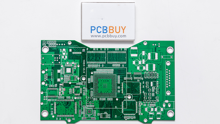
Printed Circuit Boards (PCBs) are the backbone of modern electronics. Despite their reliability, environmental factors can cause premature failure of PCBs, leading to malfunctioning devices, increased maintenance costs, and product recalls. Understanding these factors and their mechanisms is crucial to improving PCB durability.
1. Introduction
Electronic devices are often subjected to harsh environmental conditions, and PCBs are no exception. Environmental factors such as temperature fluctuations, moisture, corrosion, and mechanical stress can cause failures that degrade a PCB's performance. This article explores these environmental factors and provides insights into their impact on PCBs.
2. Temperature Stress and Thermal Cycling
2.1. Effects of High Temperatures
Excessive heat causes materials used in PCBs to expand and can result in damage. **Thermal expansion can lead to delamination, warping, and cracking of the PCB substrate and copper traces. As temperature increases, materials like FR-4 (commonly used in PCB substrates) expand at different rates than metal components, leading to interfacial failures.
Coefficient of Thermal Expansion (CTE): For instance, FR-4 has a CTE of around 16-17 ppm/°C, while copper has 16.5 ppm/°C. When subjected to thermal cycling, these small differences cause cumulative damage, especially at solder joints.
|
Material |
CTE (ppm/°C) |
|
FR-4 |
16-17 |
|
Copper |
16.5 |
|
Ceramic |
7-9 |
2.2. Thermal Cycling and Fatigue
Thermal cycling, where PCBs repeatedly heat up and cool down, can cause solder joint fatigue and failure. This phenomenon is particularly important in power electronics, where components rapidly cycle through high and low temperatures.
Chemical Reaction
The Sn-Ag-Cu solder used in most PCBs undergoes phase changes when exposed to high temperatures. Over time, these phase changes contribute to the degradation of solder joints through thermal fatigue:
Sn + Ag→ Ag3Sn (At high temperatures)
Thermal cycling-induced failures are typically seen in environments such as automotive electronics and aerospace applications.
3. Moisture and Humidity Exposure
3.1. Absorption of Moisture
PCB substrates like FR-4 absorb moisture over time. In humid environments, this moisture can lead to hydrolysis and degradation of the dielectric properties of the PCB. Water molecules can penetrate the material, causing Electromigration between conductive traces.
Electromigration: This process accelerates when moisture combines with a bias voltage across a PCB. Moisture allows ions to move between metal conductors, forming dendrites that can eventually cause shorts.
|
Condition |
Electromigration Rate (nm/year) |
|
60% RH |
0.3 |
|
85% RH |
0.7 |
3.2. Condensation and Corrosion
Condensation from rapid temperature changes, especially when PCBs move from cold to hot environments, can introduce water onto the board surface. This water, when combined with ionic residues from flux or solder paste, can corrode traces and components.
Chemical Reaction
Moisture can combine with air pollutants such as sulfur dioxide SO2 to form sulfuric acid:
SO2 + H2O → H2SO4
This acid can corrode copper traces, leading to failures.
4. Corrosion and Oxidation
4.1. Corrosive Environments
PCB materials, especially copper traces and solder joints, are prone to corrosion when exposed to certain chemicals like chlorides, sulfides, and acids. Corrosion can be exacerbated by high humidity and airborne pollutants, leading to trace thinning or complete open circuits.
4.2. Oxidation
Oxidation of metal surfaces, particularly copper, leads to an increase in resistance, impacting signal integrity. In more severe cases, oxidation can render connections useless.
Chemical Reaction
Oxidation of copper is one of the more common reactions:
Cu + O2 → CuO (Copper Oxide)
This reaction causes a greenish-black layer to form on the copper surface, which can hinder conductivity.
5. Vibration and Mechanical Shock
5.1. Vibration-Induced Failures
Vibration causes mechanical stress on PCBs, which can lead to micro-cracks in solder joints, traces, or components. Over time, these micro-cracks grow, causing intermittent or permanent failures.
5.2. Fatigue from Mechanical Shock
Frequent mechanical shocks, such as dropping devices, can dislodge components or cause solder joints to crack. High-vibration environments, such as in automotive or aerospace applications, can lead to failures without proper shock-proof design.
|
Environmental Condition |
Common PCB Failure |
|
Low-frequency vibration |
Solder joint cracks |
|
High-frequency vibration |
Trace delamination |
6. Electromagnetic Interference (EMI)
6.1. EMI Disruptions
High levels of EMI can induce unwanted currents in PCB traces, leading to functional disruptions. This is particularly relevant in high-speed circuits and RF PCBs, where signal integrity is critical.
6.2. Shielding and Mitigation
Proper grounding and shielding can reduce the impact of EMI, but improper PCB layout or faulty grounding can exacerbate the problem. Designing with **ground planes** and using **EMI shielding materials** can mitigate these risks.
7. Chemical Contaminants
7.1. Ionic Contamination
PCB surfaces contaminated by ionic compounds during the manufacturing process can lead to corrosion and failures. Contaminants such as **chlorides**, **sulfates**, and **flux residues** react with moisture and cause conductive pathways, leading to shorts or other failures.
7.2. Cleaning and Prevention
Proper cleaning techniques and contamination control during manufacturing are critical to prevent ionic contamination. Automated cleaning processes and post-assembly checks are necessary to ensure long-term PCB reliability.
8. Case Studies and Data
8.1. Automotive PCB Failure
In one case study, automotive PCBs exposed to both thermal cycling and high humidity were tested for reliability. Failure rates increased exponentially with higher thermal cycles and increased moisture.
|
Temperature Cycle (°C) |
Humidity (%) |
Failure Rate (%) |
|
-40 to 85 |
60 |
1.2 |
|
-40 to 85 |
85 |
4.5 |
8.2. Aerospace PCB Failure
Aerospace PCBs, which were subjected to constant vibration and extreme temperatures, demonstrated a clear correlation between mechanical stress and solder joint fatigue.
9. Conclusion
Environmental factors such as temperature extremes, moisture, corrosion, vibration, and EMI significantly impact the reliability and performance of PCBs. Understanding the mechanisms behind these failures allows engineers and manufacturers to design more robust PCBs that can withstand harsh environments. By implementing proper design considerations, material selection, and manufacturing processes, PCB longevity can be significantly improved.
References
1.Solder Joint Fatigue in High-Temperature Environments, Journal of Electronics Manufacturing, 2020.
2. Electromigration in PCB Materials, IEEE Transactions on Components and Packaging, 2019.
3. Corrosion of Copper in Printed Circuit Boards, Journal of Materials Science, 2018.
4. Environmental Effects on PCB Reliability, Electronics Cooling Magazine, 2021.
5. Vibration-Induced Failures in Electronics, SAE International, 2020.
Industry Category


