What Are the Requirements of PCB Technology for 5G Mobile Communication?
By:PCBBUY 05/06/2024 14:19

Over the past decade, mobile data transmission rates have increased 4,000 times. In order to cope with the growth of explosive mobile data traffic in the future, the connection of massive devices and the continuous emergence of various new services and application scenarios, the fifth generation (5G) mobile communication system came into being.
The 5G mobile communication system can provide users with fiber-optic access rate, "zero" delay experience, connection capacity of hundreds of billions of devices, consistent services for multiple scenarios such as ultra-high traffic density, ultra-high connection number density and ultra-high mobility, and intelligent optimization of business and user perception. At the same time, the 5C mobile communication system can bring more than 100 times the energy efficiency improvement and more than 100 times the bit cost reduction to the network, to achieve the overall vision of "information to the heart, everything at your fingertips".
What Is the Relationship of PCB and 5G?
The 5G mobile communication system is a very large and complex system, and its hardware components have a close relationship with the PCB board. In addition, in recent years, consumer mobile communication terminal products represented by mobile phones and tablet computers have experienced rapid development, among which the development of smart phones basically represents the development of related electronic components such as Integrated Circuit (IC), PCB product and other passive electronic devices in the past 10 years.
The development of mobile communication terminal products requires the application of smaller PCB areas, more refined lines, chip and passive device functions are constantly enhanced, while having high reliability performance. At the same time, the comprehensive screen, the high frequency of signal transmission and the continuous improvement of battery performance are also the development needs of communication terminal products.
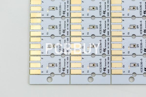
As the "mother of electronic products", PCB is an important connection carrier for various functional components and passive devices, which affects the important performance of communication terminal products. In 2003, the multilayer PCB size was generally about 130mm x50mm, which was comparable to the size of a mobile phone. At that time, the mobile phone suppliers represented by Apple and Samsung, the line width/line distance of PCB could reach 100um100pm, and the production of blind holes was realized, that is, the HDI board with 1 +n +1 structure. After more than 10 years of development, intelligent terminal products have "played a big role" in entertainment, web browsing, life, transportation and other aspects, thus promoting the function and performance of intelligent terminals.
However, the PCB did not increase the size, but reduced to about 20cm, thanks to the development of HDI technology. The PCB line width/line distance is 40pm/40m, the blind hole and buried hole are about 4m, and the use of any layer interconnection method increases the density of the intelligent terminal PCB by more than 6 times.
5G key technical index analysis
5G products will bring you infinite beautiful mobile Internet vision and experience, from a technical point of view, need to face a lot of challenges, by solving these problems, will bring a lot of technical breakthroughs and improvements.
In the 5G era, there will be a large number of MIMO antenna applications. In Massive MIMO antennas, due to the increase in the number of antenna channels, the number of channels corresponding to each antenna channel in the power amplifier will also increase correspondingly, and this change will lead to an increase in the overall power of the power amplifier, thus requiring higher power efficiency of the power amplifier. As one of the ways to improve power efficiency, how to reduce the loss of the PCB board carrying the power amplifier and improve the thermal conductivity of the PCB board has become particularly important.
In addition, the increase in the number of radiation units in the Massive MIMO antenna requires higher hardness of the PCB board to provide better support effect, and the complexity of the circuit increases, compared with the traditional double-sided PCB antenna, multi-layer plate antenna applications will be more and more.
5G communication products on PCB technical requirements and technical difficulties
PCB technical requirements for 5G communication
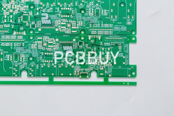
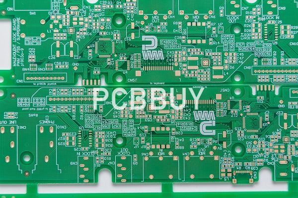
With the trend of miniaturization and increasing capacity of communication products, the design space of the front end of the product is seriously squeezed. In order to alleviate this design pressure, communication chip manufacturers have to choose to develop higher rate IC products to meet the needs of large capacity and small volume products. However, as the speed increases, the pressure on signal integrity engineers is not relieved but increased, and high speed products can be achieved using fewer lines, but the increase in speed directly leads to the strict requirements of signal quality, and the margin is becoming less and less. Under 10Gbps signal, the signal UI can reach 100ps bit width, but under 25Gbps signal, the signal bit width is only 40ps, which means that every link in the channel must be optimized to strive for each ps margin. 5G communication, as the fifth generation of mobile communication products, has applied a lot of new technologies, but in any case, it is inseparable from the PCB carrier, and the requirements for PCB are becoming more and more stringent, especially for PCB substrate materials, processing technology, surface treatment and so on.
The working frequency of 5G communication products continues to rise, bringing new requirements to the printed board production process, millimeter wave PCB is usually a multi-layer structure, microstrip line and ground coplanar waveguide circuit is usually located in the outermost layer of the multi-layer structure. Millimeter waves belong to the very high frequency (EHF) range in the entire microwave field, and the higher the frequency, the higher the dimensional accuracy of the circuit is required.
Appearance control requirements: The microstrip line in the key area is not allowed to have pitting scratches, because the high-frequency PCB line transmits not current, but high-frequency electrical pulse signals, pits, notches, pinholes and other defects on the high-frequency wire will affect the transmission, and any such small defects are not allowed.
Control microstrip antenna corners: to improve antenna gain, direction and standing wave; To avoid the resonance frequency bias to the high frequency and improve the antenna design margin, it is necessary to strictly control the Corner sharpness control (EA) of the microstrip antenna patch, such as ≤20um, 30um and so on.
For single-channel 112G high-speed products, PCB copper-clad plate materials are required to have lower Dk and Df, new resin, glass cloth and copper foil technologies are required, PCB process back drilling precision is higher, thickness tolerance control is stricter, and aperture is smaller.
HDI high-density technology application: PCB technology requirements for 5G era products include second-order HDI technology application, multiple lamination technology, asymmetric design, 0.15mm tiny hole, 0.20mm high-density hole wall spacing, mixed pressure of materials of different systems, etc.
5G communication PCB technology difficulties
5G chips require smaller PCB hole spacing, with a maximum hole wall spacing of 0.20mm and a minimum aperture of 0.15mm. Such a high-density layout brings great challenges to CCL materials and PCB manufacturing processing technology, such as CAF problems and cracks between heated holes.
0.15mm tiny aperture, the maximum aspect ratio of more than 20:1, how to prevent the problem of broken needles during drilling, how to improve the PCB electroplating aspect ratio ability, to prevent the hole wall without copper, etc., is the current PCB process needs to solve the problem.
Solution: Rapid development is the trend, the hole ring will be smaller and smaller, in order to reduce the pad warping or PP layer cracking defects, it is necessary to optimize the resin flow and pressing process parameters.
5G communication for high speed and high frequency copper clad plate technical requirements
5G communication products require higher frequencies and rates, high-speed high-frequency signals pay attention to transmission line loss, impedance and timely delay consistency, and finally receive the appropriate waveform and eye map at the receiving end, and the width of the eye map determines the time interval at which the received waveform can be sampled and regenerated without crosstalk. Obviously, the best sampling time should be chosen at the moment of maximum eye opening, and the collapse of the open eye graph is directly caused by loss. The smaller the media loss Df, the greater the height of the eye graph and the greater the noise capacity.
For PCB substrate materials, the Dk/Df needs to be smaller, the higher the Df, the more obvious the lag effect, the industry's research hotspots on PCB coppers, mainly focused on the development of Low Dk/Df, Low CTE, high thermal conductivity materials, requiring copper foil, glass cloth, tree grease, fillers and other supply chain upstream and downstream support;
Lower loss copper clad material requirements
In the next 3-5 years, the 5G communication of the Internet of everything will be mass-produced, and the 6G of the Internet of Heaven and Earth will begin pre-research, which will require high-speed copper clad plate technology to develop in the direction of lower loss Df, lower dielectric constant Dk, higher reliability and lower CTE technology. Correspondingly, the copper clad plate is mainly composed of copper foil, resin, glass cloth, fillers, etc., and should also be developed in this direction.
Lower loss resin material
In order to meet the requirements of 5G communication high-speed products, the traditional FR4 epoxy resin system can no longer meet the requirements, requiring the copper clad sheet resin Dk/Df to be smaller, and the resin system is gradually closer to the mixed resin or PTFE material.
The PCB thickness of 5G communication high-speed and high-frequency products is getting higher and higher, the aperture is getting smaller and smaller, and the PCB aspect ratio will be larger, which requires the copper clad plate resin to have lower loss, and at the same time, the hole wall separation or hole wall fracture can not occur.
Higher reliability copper clad sheet
The integration of 5G communication products is getting higher and higher, the PCB design density has been reduced from 0.55mm hole spacing to 0.35mm, the board thickness of multi-stage HDI process PCB has been increased from 3.0mm to 5.0mm, the MOT temperature requirement has been increased from 130℃ to 150℃, and the heat resistance of copper clad plate is required to be better. CAF resistance is also higher.
What Are the 5G Communication Challenges to PCB Processes?
Material requirements: A very clear direction for 5G PCB is high-frequency high-speed materials and boards. In terms of high-frequency materials, it can be clearly seen that leading material manufacturers in the traditional high-speed field such as Lianmao, Shengyi, Panasonic have begun to lay out high-frequency plates and launched a series of new materials. This will break the current high frequency plate field Rogers a dominant situation, after healthy competition, the performance of the material, convenience, availability will be greatly enhanced. Therefore, the localization of high-frequency materials is an inevitable trend.
In terms of high-speed materials, 400G products need to use M7N, MW4000 grade materials. In the backplane design, the M7N is already the lowest loss option, and the future larger capacity backplane/optical module will require lower loss materials. The combination of resin, copper foil and glass cloth will achieve the best balance between electrical performance and cost. In addition, high height and high density also pose reliability challenges.
PCB design requirements: the selection of plates should meet the requirements of high frequency and high speed, impedance matching, layering planning, wiring spacing/holes, etc. should meet the signal integrity requirements, which can be started from the six aspects of loss, embedding, high frequency phase/amplitude, mixed pressure, heat dissipation, PIM.
Process requirements: The improvement of 5G-related application product features will increase the demand for high-density PCBS, and HDI will also become an important technology area. Multi-stage HDI products and even products with arbitrary order interconnection will become popular, and new processes such as buried resistance and buried capacity will also have increasing applications.
PCB copper thickness uniformity, line width accuracy, interlayer alignment, interlayer medium thickness, back drilling depth control accuracy, plasma decontamination ability are worthy of in-depth study.
Requirements for equipment and instruments: high-precision equipment and pre-treatment line with less coarsening of copper surface are currently ideal processing equipment; The test equipment is passive intermodulation tester, flying needle impedance tester, loss test equipment, etc.
Precision graphics transfer and vacuum etching equipment, real-time monitoring and feedback of data changes in line width and coupling spacing detection equipment; Electroplating equipment with good uniformity and high-precision laminating equipment can also meet the production needs of 5G PCB.
Requirements for quality control: Due to the improvement of 5G signal rate, the deviation of the board has a greater impact on signal performance, which requires the production deviation control of the board to be stricter, and the existing mainstream board process and equipment are not updated, which will become the bottleneck of future technological development. How PCB manufacturers break the game is crucial.
What Are 5g PCBs Design Hints?
The style of a printed circuit board for 5G applications is entirely centered on the handling of mixed high speed and high frequency signals. In addition to the standard rules regarding the design of 5g circuit boards with high frequency signals, it is necessary to pick the materials appropriately so that you can prevent power losses and guarantee the integrity regarding the signal. In addition, EMI which could arise between your parts of the board that manage analog signals and those that handle digital signals should be prevented, thus meeting the FCC EMC requirements. The 2 parameters that guide the option of the material are thermal conductivity and thermal coefficient of dielectric constant, which describes changes in the dielectric constant (typically in ppm/°C). A substrate with high thermal conductivity is actually preferable, since it is able to easily dissipate the warmth made by the components. The thermal coefficient of dielectric constant is an equally important parameter, as variations within the dielectric constant can induce dispersions, which in turn can stretch digital pulses, replace the signal propagation speed and in some cases also produce signal reflections along a transmission line.
PCB geometry also plays a simple role, where geometry means laminate thickness and transmission line characteristics. Pertaining to the initial point, it’s important to choose a laminate thickness which can be typically between 1/4 and 1/8 of highest operating frequency’s wavelength. If the laminate is just too thin, there is a risk of it resonating, and on occasion even propagating the waves through the conductors. Pertaining to transmission lines, it’s important to decide which type of conductor you intend to use: microstrip, stripline, or grounded coplanar waveguide (GCPW). Microstrips are one of the most familiar ones, but they have problems with radiated losses and spurious mode propagation above 30 GHz. Striplines are a valid solution, too, but they are tough to manufacture and for that reason more costly. In addition, microvias is employed to connect the striplines to your outermost layers. GCPWs are a fantastic choice but they offer higher conduction losses than microstrips and striplines.
After selecting the substrate material, designers shall proceed with the common rules applicable to high frequency 5g circuit board design: utilize the shortest possible tracks and check both the width together with distance between your tracks in order to keep consitently the impedance constant along all the interconnections. Here are some recommendations, or hints, useful for designing a PCB for 5G applications:
Choose materials with low dielectric constant (Dk)
Since Dk losses increase proportionally with the frequency, it is crucial to select materials utilizing the lowest possible dielectric constants;
Use little solder mask
Most solder masks have a top moisture absorption capacity. In the event this happens, high losses can happen when you look at the circuit;
Use perfectly smooth copper traces and plans
The existing skin depth, in fact, is inversely proportional towards the frequency and so, on a 5g circuit board with high frequency signals, it is very shallow. An irregular copper surface will offer you the existing an irregular path, increasing the resistive losses;
Signal integrity
High frequencies represent the most difficult challenges for the integrated circuit designer. To be able to maximize I/O, high density interconnections (HDI) require thinner tracks, a factor that will cause signal degradation leading to further losses. These losses adversely affect the transmission of this RF signal, which can be delayed for a couple of milliseconds, in turn causing problems in the signal transmission chain. In high frequency domain, signal integrity is almost entirely based on checking impedance.
Traditional PCB manufacturing processes, for instance the subtractive process, have the disadvantage of making tracks with a trapezoidal cross section (the angle, when compared to vertical perpendicular to the track, is normally between 25 and 45 degrees). These cross sections modify the impedance for the tracks themselves, placing serious limits on 5G applications. However, the difficulty could be solved using the mSAP (Semi-Additive fabrication Process) technique, that allows generating traces with greater precision, allowing trace geometries to be defined via photolithography. In the following figure we are able to see an assessment regarding the two manufacturing processes.
Reference
He Wei, PCB Basic Electrical Information Science and Technology, China Machine Press,425-428
Industry Category


