What Does A Sensor PCB Do for PCB Layout Process?
By:PCBBUY 08/17/2022 15:58

In this passage, we are providing all the information of PCB sensor. If you are curious about Sensor PCB, please check and read the content below for more information.

What is the process of Sensor PCB layout?
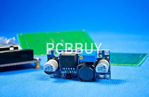
When it comes to mounting CMOS sensors, you will usually use a through-hole or surface mount. In some cases, these sensors might be in the form of a die that you can mount to a BGA package. However, you can also integrate other sensors with the signal processing block. The single SoC (system-on-chip) approach requires four or more layers to keep in mind during stack-up management.
You should use that layer number to set a ground layer below the surface one with the CMOS sensor. The ground plane must have different areas for digital and analog sections. It might not be wise to go with a ground plane split since you may encounter issues with noise sensitivity. You also don’t want any circuits with a high frequency or high speed near the sensor, so consider placing them far away from it.
What are the common issues of Sensor PCB layout?
Even a brilliant design can run off the rails when it involves sensors deployed on a printed circuit board, as engineers familiar with the process know far too well.
Take Duane Benson, for example, who has been designing embedded systems for manufacturing for 15 years. While his formal title is director of marketing at Milwaukee Electronics, he has spent plenty of time on the manufacturing floor at Screaming Circuits, the company’s online prototype and on-demand manufacturing unit. And here he has pretty much seen it all.

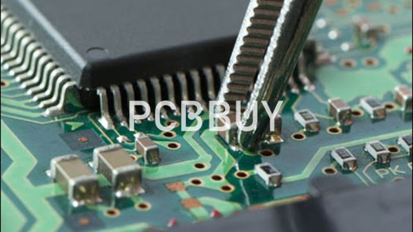
One of the more common mistakes that engineers make with sensors in a PCB layout has to do with the location of vias (plated holes used to take signals from one PCB layer to another). “When space is limited, it’s pretty tempting to put that via in the middle of the component solder pad,” he said. But when soldered, the result can be a poor solder joint on one side of the board and a pool of solder on the other side. Capillary action of the via will draw the solder from the pad, where you want it, to the other side of the board where you don’t.”
Fortunately, in small production volumes there are workarounds for this problem. “We may put heat-resistant tape on the backside and fill the via with solder,” he said.
Another solution is to put extra solder on the pad. Yet another fix is to fill the via holes with higher temperature solder. But all those fixes take time, cost money and put reliability at risk. And none of those solutions will work with small components like ball grid array (BGA) packaged parts or in a large-scale, volume production. Try to put vias in tiny BGA pads, and the ancient engineering adage comes into play: “When in doubt, throw it out and start over,” Benson said.
What are the applications of PCB sensor?
Different types of sensors have their place in different applications, and the list of sensors you need to include is dictated by what you need to measure. The electronic sensors industry has taken great pains to design systems that provide detection of a long list of physical phenomena, ranging from electromechanical vibrations to chemical and biological measurements.
When you work with the right design software, you’ll have the capabilities you need to satisfy basic electrical and mechanical requirements in your device while incorporating the sensors and other functionality you want. Here are some ideas for different types of sensors you can use in your next sensor module or mobile/IoT device:
What are the considerations of Sensor PCB layout?
The simplest sensor for detecting infrared light is a photodiode. This sensor is easy to include in any PCB and allows quick detection of infrared light from a point source. For weak optical signals, avalanche photodiodes can be used to provide some gain, providing more reliable detection of infrared or visible light.

When it comes to thermal imaging, you’ll need to use a CCD in your PCB as the array of discrete photosensitive pixels provides the spatial resolution required to form an image. This provides thermal monitoring over a large field of view. Contrast this with a photodiode, which has lower sensitivity and can only be used to detect light from a single point.
How to select sensors?
Selecting sensors for use in new connected products is about more than considering the phenomena you need to measure. You’ll need to consider the environment where the product is deployed and how the product will be used when determining which types of sensors and the specific sensors you need in your device.
The design and functionality requirements for your device are the first place to start considering which sensors your device needs to operate. Different types of sensors have different levels of accuracy, limit of detection, measurement range, form factor, power requirements, and breadth of capabilities. You’ll need to balance the required capabilities with your device’s mechanical footprint and enclosure when selecting sensors to include in your design.
As an example, if you are creating a wearable environmental monitor for use in a factory, you’ll need to balance the required level of accuracy and measurement range with the requirement to keep the device small enough to be worn. If your monitor needs to detect specific noxious gases, you don’t need to detect down to ppb levels if unsafe exposure reaches high ppm levels. In general, sensors with a lower limit of detection will also carry a greater cost, which becomes important if your device will be produced with high volume.
Industry Category


