What Is Electronic Components Replacement in PCB?: A Comprehensive Guide
By:PCB 10/21/2024 16:34
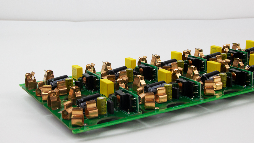
Printed Circuit Boards (PCBs) are integral to modern electronics, serving as the foundation for various devices. Over time, components on these boards may fail or need replacement due to wear, environmental conditions, or upgrades. This article provides a thorough overview of electronic component replacement in PCBs, covering principles, processes, and considerations.
What Are Types of Electronic Components?
PCBs consist of various electronic components, each serving specific functions:
1. Resistors: Control the flow of electric current and divide voltages.
2. Capacitors: Store and release electrical energy.
3. Inductors: Store energy in a magnetic field.
4. Diodes: Allow current to flow in one direction only.
5. Transistors: Amplify or switch electronic signals.
6. Integrated Circuits (ICs): Perform complex functions in compact forms.
What Are Component Specifications?
When replacing components, it's essential to consider specifications such as:
Resistance (Ω) for resistors.
Capacitance (F) for capacitors.
Voltage ratings (V) for all components.
Power ratings (W) for resistors and other components.
|
Component Type |
Unit |
Typical Value Range |
|
Resistor |
Ω |
1 - 1M |
|
Capacitor |
F |
1pF - 1000μF |
|
Inductor |
H |
1μH - 100H |
|
Voltage |
V |
5V - 1000V |
|
Power |
W |
0.1 - 1000 |
What Are Principles of Component Replacement?
Basic Electrical Principles
Understanding the electrical properties of components is crucial for effective replacement. The fundamental laws governing electrical components include Ohm's Law and Kirchhoff's Laws.
Ohm's Law
Ohm's Law states that the current (I) flowing through a conductor between two points is directly proportional to the voltage (V) across the two points and inversely proportional to the resistance (R) of the conductor:
V = I X R
Kirchhoff's Laws
1. Kirchhoff's Current Law (KCL): The total current entering a junction equals the total current leaving the junction.
2. Kirchhoff's Voltage Law (KVL): The sum of the electrical potential differences around any closed network is zero.
Chemical Properties
Some components, like capacitors and batteries, rely on chemical principles. For instance, the dielectric material in capacitors influences capacitance and energy storage capabilities.
Capacitor Equation
The capacitance (C) of a capacitor is defined by the equation:

Where:
C is capacitance in Farads (F),
Q is the charge in Coulombs (C),
V is the voltage in Volts (V).
The Replacement Process
Step 1: Identifying Faulty Components
Visual Inspection
Look for signs of damage, such as burnt components, discoloration, or swelling.
Testing with a Multimeter
For Resistors: Measure resistance to check for open or short circuits.
For Capacitors: Use the capacitance setting to verify value and test ESR.
For Diodes: Test in both directions; a good diode should conduct in one direction only.
Step 2: Selecting Replacement Parts
Specifications Match
Ensure the replacement component matches or exceeds the original specifications (e.g., voltage rating, resistance).
Equivalent Components
Sometimes, equivalent components can be used. Verify that they have similar electrical characteristics.
|
Parameter |
Original Component |
Replacement Component |
|
Resistance (Ω) |
1kΩ |
1kΩ (5% tolerance) |
|
Voltage (V) |
50V |
63V |
|
Capacitance (F) |
10μF |
10μF (tantalum) |
Step 3: Preparing for Replacement
Tools Required
- Soldering iron
- Desoldering pump or wick
- Tweezers
- Multimeter
- Isopropyl alcohol (for cleaning)
Safety Precautions
Always wear safety goggles and work in a well-ventilated area.
Step 4: Removing the Faulty Component
1. Heat the Solder: Use a soldering iron to melt the solder.
2. Desoldering: Quickly remove solder using a desoldering pump or wick.
3. Clean the Area: Clean the PCB pads with isopropyl alcohol to prepare for the new component.
Step 5: Installing the New Component
1. Align the Component: Position the new component on the PCB pads.
2. Soldering: Apply solder while ensuring the component is secure.
Step 6: Testing the Repaired Circuit
Once the new component is installed, conduct functional tests to ensure the circuit operates correctly.
Considerations for Component Replacement
Compatibility Issues
Ensure that the replacement component is compatible with existing circuit specifications and layout.
Quality of Components
Opt for high-quality components to enhance reliability. Check for reputable manufacturers and compliance with standards like RoHS and CE.
Environmental Conditions
Be aware of the operational environment of the PCB. Components should be rated for factors like temperature and humidity.
Common Challenges in Component Replacement
Soldering Issues
Cold Solder Joints: Caused by insufficient heating, leading to poor connections.
Solder Bridges: Excess solder can create unintended connections between pads.
Component Availability
Older components may be difficult to source. Consider using equivalent components when necessary.
PCB Damage
Take care to avoid damaging the PCB during component removal. Excessive heat can lift pads or damage traces.
Conclusion
Replacing electronic components in PCBs requires skill, knowledge, and attention to detail. By following the steps outlined in this guide, technicians can effectively troubleshoot and replace faulty components, ensuring the longevity and reliability of electronic devices.
References
1. Paul Horowitz, Winfield Hill, "The Art of Electronics," Cambridge University Press.
2. Howard M. Berlin, "PCB Design Tutorial," Advanced Circuits.
3. "Component Replacement Guidelines," Electronics Tutorials, [Website link].
4. "Understanding Capacitors and Their Applications," IEEE Journals.
Industry Category


