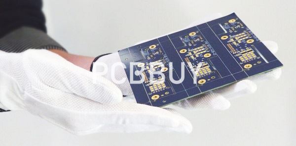
What Is Quick Turn PCB & How to Get PCB?
By:PCBBUY 01/12/2022 09:50

Printed circuit board has good product consistency, it can adopt standardized design, is conducive to the mechanization and automation in the production process. At the same time, the whole printed circuit board after assembly and debugging can be used as an independent spare part to facilitate the exchange and maintenance of the whole machine products.
If you are going to learn the knowledge about the process of PCB manufacturing, you can check and read the content to get more information about quick turn PCB.
What is the structure of PCB?
There are four main parts to a PCB:
· Substrate: The first, and most important, is the substrate, usually made of fiberglass. Fiberglass is used because it provides a core strength to the PCB and helps resist breakage. Think of the substrate as the PCB’s “skeleton”.
· Copper Layer: Depending on the board type, this layer can either be copper foil or a full-on copper coating. Regardless of which approach is used, the point of the copper is still the same — to carry electrical signals to and from the PCB, much like your nervous system carries signals between your brain and your muscles.
· Solder Mask: The third piece of the PCB is the solder mask, which is a layer of polymer that helps protect the copper so that it doesn’t short-circuit from coming into contact with the environment. In this way, the solder mask acts as the PCB’s “skin”.
· Silkscreen: The final part of the circuit board is the silkscreen. The silkscreen is usually on the component side of the board used to show part numbers, logos, symbols switch settings, component reference and test points. The silkscreen can also be known as legend or nomenclature.
What is the process of quick turn PCB?
Prototypes
Here at Avanti Circuits, we can offer you a prototype PCB. A prototype features a pattern that was used on another version of a PCB. Prototypes are used for inspection so that the customer can make adjustments to it should they need to.
PCB Prototypes are often used to help manufacturers determine if there are any defects in the original PCB. It allows us to improve efficiency and performance. Once a PCB has been made it is hard to make changes, this is why prototypes are crucial.
The Manufacturing Process
PCB’s can be turned around in just 24 hours in some cases. This allows the customer to save money on manufacturing the PCB themselves. It also allows them to concentrate on other aspects of their work.
The Assembly Process
It can take just 24 hours to ensure a PCB is assembled for a customer. We understand that time is of the essence which is why we ensure all of our PCB’s are manufactured quickly.
In order for the assembly process to be undertaken quickly the PCB’s design needs to be fastened. There are different assembly types available such as:
· Mixed technology. This is a combination of the thru-hole and surface mount.
· Single or double-sided placement. This is where the manufacturer places the components on 1 or both sides of the circuit board.
· Surface mount. This is known as “SMT” by many manufacturers.
· Thru-hole.
During the assembly, different solder types can be used. Once the assembly process is complete the PCB is inspected to ensure its functioning correctly.

What are the laminations of quick turn PCB?
With standard technology—single lamination, through hole, two, four, six and eight-layer boards… a one to three-day turn is fairly routine. But a quickturn PCB prototype can only be as quick as the information provided and the technology you are working with. You need to be aware of a few things that can slow down a quickturn.
Laminations
Let’s start with multiple laminations. Every time you laminate a board, it is like building another multilayer board. The board goes back through all the early fabrication steps. Each lamination cycle usually adds two days to the process. This doesn’t mean that multiple laminations aren’t ever necessary, of course. But the process is inherently going to conflict with quick turn efforts, and as such should be used sparingly in quickturn PCB prototype designs.
Via-in-Pad Plated Over
Another example is via-in-pad plated over, applicable to single lamination stack-ups. If you have a surface mount footprint with vias in the pad, it can cause solder to wick into the hole. Sometimes this process may be required to keep heat out from under the component, or as a means of saving space. While via-in-pads have become very common, be aware that it can add at least a day to the cycle time.

Fabrication Drawing
Be aware of the notes you put on your fabrication drawing. Know what your notes mean to the fabricator.
Another example is via-in-pad plated over, applicable to single lamination stack-ups. If you have a surface mount footprint with vias in the pad, it can cause solder to wick into the hole. Sometimes this process may be required to keep heat out from under the component, or as a means of saving space. While via-in-pads have become very common, be aware that it can add at least a day to the cycle time.
Fabrication Drawing
Be aware of the notes you put on your fabrication drawing. Know what your notes mean to the fabricator.
Industry Category


