What Is a PCB Connector and What Is the Function of It?
By:PCBBUY 12/13/2021 09:40

PCB connectors are mounted on the PCB and are typically used to transfer signals or power from one PCB to another, or to transfer to or from the PCB from another source within the unit. Connectors provide an easy method of Design for Manufacture, as the PCBs are not hard-wired to each other and can be assembled later in a production process.
Do you know the information of PCB Connector? If you are going to learn more knowledge about PCB Connector, please check and read the content in this passage.
What are the main types of PCB connector?
We have countless electronics that use PCB board connectors. As a result, the design must suit the type, size, and function. With this, there are numerous PCB connector types available.
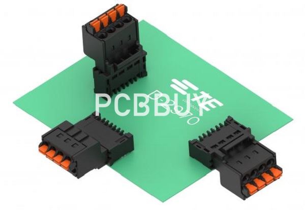
Wire-to-board Connectors
It is a PCB connector type that connects a wire to a printed circuit board. The device makes it easy to have connections between circuits.
Board-to-board Connectors
Board-to-board Connectors allows manufacturers to connect PCB without a cable. This connection allows for a signal connection between two PCBs. It can be a permanent connection that will require a "fit and forget" approach. The device connects two PCBs using pins and receptacles.
Male PCB Connectors / Pin headers
Also known as pin headers, these are simply a row of pins with different spacing. The spacing could be 0.1, 0.2, 0.197 inches apart.
Female PCB Connectors:
We also call this the socket or header receptacles. It accommodates the male connector tightly, which creates a through the passage for the signal (power or data)
Backplane Connectors
It is a particular type of PCB connector that can connect with other PCBs. It helps increase data rates and reduce signal rise. The backplane connector is a support structure that allows connection for other PCBs. It also serves as a plane to enable users to integrate other system components known as a daughterboard.
USB PCB Connector
It is the most common type of PCB connector today. It is not surprising as the USB connector finds application in many devices we use. Examples are tablets, keyboards. Smartphones, digital camera, computer mice, and others
How to test PCB connector?
Prototyping and testing circuits can prove an arduous task, and therefore, you will not desire to solder on these permanent connectors already talked about. In such instances, it becomes essential to prototype and test connectors as an alternative. Such an approach will allow you to alter the fly, devoid of any need for resoldering parts on the PCB.

The connector types involved include the following.
· Banana connectors. Connectors of these kinds get used in electronic test machines or equipment such as multimeters and entail multiple or single banana jack connectors. The male jack plugs into the female banana plug, thereby establishing a sole power connection.
· Alligator clips. The connector type proves perfect for experimenting with diverse connections during the circuit test run. However, you cannot rely on the durability of these connectors because, by design, they should only get used temporarily. Therefore, it becomes common to find yourself potentially wrestling with its slippery grips besides generating unintended short-circuits, especially when you happen to touch the surrounding metals.
· IC clips. It comes as a connector loaded with finesse and one that can get used by attaching them to the IC‘s pins without the risk of touching the surrounding pins. The attribute makes it perfect for troubleshooting needs.
Plenty of connector types exist, and it becomes impossible to discuss every type in this article. You may have noticed that some connector types like the D-sub and the RJ have not been featured. D-sub connectors prove common and a classic for computers and come in diverse types based on the number of pins each contains besides the shell size holding the pins. The connectors prove crucial for providing communication and power abilities between two electronic devices.
Industry Category


