What Is a PCB Protected Battery for PCB Beginners?
By:PCBBUY 12/14/2021 09:21

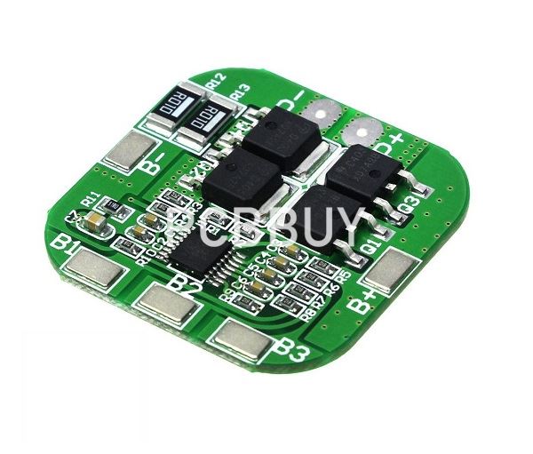
PCB is an indispensable part of lithium battery. It play a role in charge and discharge protection of the series and parallel battery packs. And at the same time it can detect the overvoltage, overcurrent, overtemperature, undervoltage and short circuit status of each single cell in the battery pack to extend the battery life, therefore it is the must have to avoid the lithium battery or battery pack from explosion, fire and damage.
In this passage if you are going to learn more about PCB protected battery, please check and read the content for more professional information.

What is the basic information of PCB protected battery?
The lithium battery protection board also has a equilibrium protection function, which has two modes of energy consumption and energy conversion. Energy dissipation equilibrium refers to consume excess power of the battery pack or the single cell with high voltage through the use of internal resistance. Energy consumption balancing is divided into balancing during charging, fixed-point voltage balancing, and static automatic balancing.
What are the working principles of PCB protected battery?
When the protection board is normal, Vdd is high level, Vss, VM is low level, DO and CO are high level. When any parameter of Vdd, Vss, VM is changed, the level of DO or CO will be change has occurred.
Overcharge detection voltage
In the normal state, Vdd gradually rises to the voltage between VDD and VSS when the CO terminal changes from a high level to a low level.
Overcharge release voltage
In the state of charge, Vdd gradually decreases to the voltage between VDD and VSS when the CO terminal changes from low level to high level.
Over discharge detection voltage
In the normal state, Vdd gradually decreases to the voltage between VDD and VSS when the DO terminal changes from a high level to a low level.
Over discharge release voltage
In the overdischarge state, Vdd gradually rises to the voltage between VDD and VSS when the DO terminal changes from low level to high level.
Over current 1 detection voltage
In the normal state, the VM gradually rises to the voltage between VM and VSS when DO changes from high level to low level.
Over current 2 detection voltage
In the normal state, the VM rises from OV at a speed of 1 ms or more and 4 ms or less to the voltage between VM and VSS when the DO terminal changes from a high level to a low level.
Load short-circuit detection voltage
In the normal state, the VM rises at a speed of 1 μS or more and 50 μS or less from OV to the voltage between VM and VSS when the DO terminal changes from a high level to a low level.

What is the working process of PCB protected battery?
When the cell voltage is between 2.5V and 4.3V, the first pin and the third pin of DW01 both output high level (equal to the supply voltage), and the second pin voltage is 0V. At this time, the voltage of pin 1 and pin 3 of DW01 will be applied to pins 5 and 4 of 8205A respectively. The two electronic switches in 8205A are in the conducting state because their G poles are connected to the voltage from DW01, that is Both electronic switches are in the open state. At this time, the negative pole of the battery is directly connected to the P- terminal of the protection board, and the protection board has a voltage output.
When the cell is discharged through an external load, the voltage of the cell will slowly decrease. At the same time, the DW01 will monitor the cell voltage in real time through the R1 resistance. When the cell voltage drops to about 2.3V, DW01 will consider that the cell voltage has been In the over-discharge voltage state, immediately disconnect the output voltage of the first pin, so that the voltage of the first pin becomes 0V, and the switch tube in the 8205A is closed because there is no voltage on the fifth pin. At this time, the B- of the battery cell and the P- of the protection board are in a disconnected state.
That is, the discharge circuit of the battery cell is cut off, and the battery cell will stop discharging. The protection board is in an over-discharged state and has been maintained. After the P and P- of the protection board have indirect charging voltages, DW01 will immediately stop the over-discharge state after B- detects the charging voltage, and output a high voltage at pin 1 again to turn on the over-discharge control tube in the 8205A. That is, the B- of the battery cell and the P- of the protection board are reconnected, and the battery is directly charged by the charger.
What are the differences of PCB and BMS?
When deciding to choose a battery management system to help with protection of your battery, you need first to consider the function. The PCM and PCB are used for small battery packs, and they offer low levels of protection. While on the side, BMS has the functions of PCM and other additional properties. When it comes to pricing, the PCM is cheaper compared to the BMS. The best way to get a solution on what to use is to consider the two factors.

For every lithium battery PCB, the protection against overheating is critical. But this also does not mean other measures are not required to ensure that operations are safe when dealing with electronics with lithium batteries.
The primary safety circuits’ primary functions include undervoltage, overvoltage, over-temperature, under-temperature, and overcurrent. Some other safety circuits are world-class and contain a secondary safety circuit. This second circuit protects the cell in case the first safety fails.
Industry Category


