What is EMI in PCB through 4 Essential Tips for Beginners?
By:PCBBUY 11/18/2021 09:25

To create EMI, all you need is energy and an antenna. Electronic devices are basically boards teeming with electromagnetic energy. All you need is a dipole across an energy source, and you’ve got an antenna that can radiate EMI. What’s more, because EMI radiation can affect critical electronics in the world around us, such as the equipment on an airplane, there are EMI/EMC regulations and standards you have to pass before your product can go to market. Let’s dive into the common techniques you can employ to reduce EMI in your PCB designs.
Do you know what EMI in PCB is? If you are curious about the basic knowledge about EMI in PCB, please check and read the content below for more information.

1. What are the main types of EMI in PCB?
Sources of electromagnetic interference are all around us, and we can categorize them in several ways:
Source: Human-made EMI arises from electronic circuits. Naturally occurring EMI, on the other hand, can arise from environmental factors like cosmic noise and lightning.
Duration: Continuous interference is an EMI source that emits a constant signal, which most often appears as background noise. Impulse interference is intermittent, usually caused by switching systems, lightning and other non-constant sources.
Bandwidth: Narrowband signals like those used by radio can encounter interference from oscillators and transmitters, though these sources only affect certain parts of the spectrum intermittently. Broadband interference affects high-data signals like TV and can come from many sources, including arc welders and solar noise.
2. How to process EMI shielding?
Some components will produce EMI no matter what design rules you follow — especially small, high-speed parts. Fortunately, shielding and filtering can keep this EMI’s effects to a minimum. Some shielding and filtering options include the following:

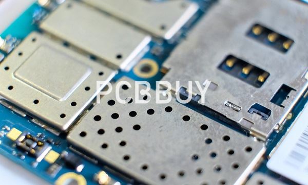
Component and board shielding: Physical shields are metallic packages that encapsulate all or part of a board. Their goal is to keep EMI from entering the board’s circuitry, though the specific methods vary based on the EMI’s source. For EMI that comes from within the system, component shields may be used to encase a specific component that produces EMI — thus connecting to ground, reducing the antenna loop size and absorbing EMI. Other shields may encase the entire board to protect against EMI from outside sources. A Faraday Cage, for example, is a thick protective enclosure designed to block RF waves. These devices are usually made of metal or conductive foam.
Low-pass filtering: Sometimes, a PCB can include low pass filters to eliminate high-frequency noise from components. These filters suppress the noise from these part, allowing the current to continue on the return path without interference.
Cable shielding: Cables that carry analog and digital currents create the greatest amount of EMI issues. They produce these issues by producing parasitic capacitance and inductance — a particular problem for high-frequency signals. Fortunately, shielding these cables and connecting them to ground at the front and back helps cancels out EMI interference.
3. What are the challenges of EMI in PCB?
The general effects of electromagnetic interference between electronic devices are noticeable. Wireless communication systems are interrupted by unexpected broadcasts, automotive systems may malfunction, and advanced sensors used in medical or other applications may not transmit the complete or correct data. Flight attendants still make a similar request before the takeoff and landing of commercial flights. Even back in CB radios’ days, we learned to avoid revving our cars’ engines to reduce the engine noise from our transmissions. But EMI prevention goes much further than that, and there are many different design standards in place to specify how much interference is or isn’t allowed:
IEC 60601-1-2 is a series of standards that define medical equipment’s essential performance and safety expectations when confronted with EMI.
CISPR 12 is a regulatory requirement to ensure that automobiles’ internal combustion engines do not interfere with wireless communication when the vehicle is near residences or businesses.
CISPR 25 ensures the performance of radios and other communication equipment mounted in vehicles equipped with internal combustion engines.

4. What are the considerations of EMI in PCB?
Bend requirements
Each shielding approach contributes to the flexible circuit’s total thickness. Since the minimum bend capacity is a function of thickness, it will restrict or reduce a flex PCB’s bendability. As part of the design and material selection process, the minimum bend radius and bend type requirement for shielded designs must be precisely established and evaluated.
Additional restrictions are imposed by the type of bend required, whether static or dynamic. The bending capacity of a dynamic flex board is significantly greater than that of a static bend design.
Controlled impedance
The EMI and RF shielding approach is further limited by controlled impedance signal requirements in flexible PCBs. The shield(s) must have electrical properties that meet both EMI and reference plane criteria in order to obtain the appropriate regulated impedance values. Not all shielding techniques meet both the requirements.
Industry Category


