What is High Frequency PCB and How to Design It?
By:PCBBUY 12/10/2021 09:19

High frequency circuits are often highly integrated and with high wiring density. The use of multilayer board is both a necessary and an effective means to reduce interference. In PCB layout stage, a reasonable choice of a certain size and layers PCB, can make full use of an intermediary to set up the block, better nearby grounding, and effectively reduce the parasitic inductance and shorten the length of the transmission of signals, but also can greatly reduce the cross interference of signals etc., all of these methods are good for the reliability of the high frequency circuit.
In this passage, we will provide you all the details of high frequency PCB. If you are curious about the knowledge of high frequency PCB, please check and read the content below in this passage.
What are the features of high frequency PCB?
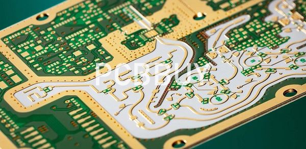
· We are familiar with the word PCB, some of you who are not, it is an acronym of Printed Circuit Board which uses conductive tracks and paths to electronically connect different components on the board.
· Copper is used to provide conductive path on the board which is laminated on the substrate material which is mostly made up of epoxy resin.
· Signal communication plays a vital role in electronic projects specially when it comes to WiFi and satellite system.
· Where there is a need of signal communication between two objects, there is a need of high frequency boards.
· High Frequency PCB is a type of PCB used for signal transmission in the variety of applications including mobile, microwave, radio frequency and high speed design applications.
· High Frequency boards come with high frequency laminates are difficult to fabricate because they need to maintain thermal heat transfer of the application, in view of the sensitivity of the signal.
· Special materials are used to attain the high frequency given by the High Frequency PCB.
What are the requirements of choosing high frequency PCB material?
Special materials are required to achieve the high frequency provided by this type of printed circuit board - any changes in the Er value of these materials can affect the impedance of the board. Many PCB designers turn to Rogers dielectric material for its lower dielectric loss, reduced signal loss, lower cost of circuit fabrication and better suitability for fast-turnaround prototyping applications.
Apart from choosing the appropriate PCB material and determining the correct the value of the Er, designers should take parameter such as conductor width and spacing, substrate constant into consideration. These parameters must be exactly specified and implemented with the highest level of process control.
High-frequency boards, e.g. for wireless applications and data rates in the upper GHz range have special demands on the material used:
Adapted permittivity
Low attenuation for efficient signal transmission
Homogeneous construction with low tolerances in insulation thickness and dielectric constant
For many applications, it is sufficient to use FR4 material with an appropriate layer buildup. In addition, we process high-frequency materials with improved dielectric properties. These have a very low loss factor, a low dielectric constant, and are primarily temperature and frequency independent.
What are the properties of high frequency PCB?
High frequency PCBs offer a wide range of properties. Understanding these properties helps you to understand these PCBs. These printed circuit boards are called high frequency PCBs because of the properties they offer. Let us have a look at the properties of these PCBs.
Dissipation factor: HF PCBs have a low dissipation factor which falls between 0.0019 and 0.025. This value helps to ensure that the signal transmission rate isn’t affected. Low dissipation factor also enables improved signal transmission. A lower dissipation factor can help to minimize signal loss.
Low and stable dielectric constant: The dielectric constant of a high frequency PCBs is lower and stable. This helps to ensure frequency transmission. This also ensures less signal delay. Lower dielectric constant leads to higher rate of frequency transmission.
Chemical resistance: High frequency PCBs can withstand chemicals. These boards can survive chemical attack when exposed to one. Due to this property, these circuit boards are less likely to corrode.
What are the applications of high frequency PCB?
High frequency PCB’s are used in the following applications:
· Automotive Radar Systems
· Global Positioning Satellite Antennas
· Cellular Telecommunications Systems – Power Amplifiers and Antennas
· Direct Broadcast Satellites
· E-band Point to Point Microwave Links
· RF Identification (RFID) Tags
· Airborne and Ground Based Radar Systems
· Millimeter Wave Applications
· Missile Guidance Systems
· Space Satellite Transceivers
Industry Category


