PCB temperature
By:PCBBUY 05/26/2021 17:50

There are several factors will influence the PCB manufacturing process, performance and quality. And among all the factors, temperature as a very important element, affects the safety, reliability and performance of PCB. High temperatures can quickly lead to malfunctions and permanent damage.
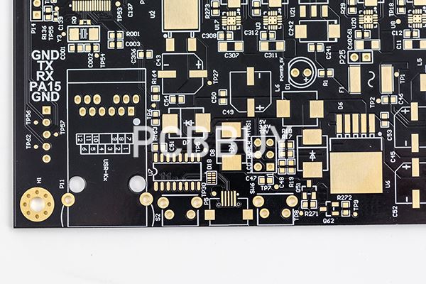
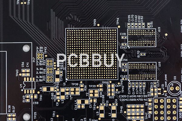
The physical shape of a PCB is made up of traces, holes, layers, through holes, and solders masks. Each of these things can be affected by PCB product temperature. A snowball effect of problems can occur if PCB temperatures rise linearly. If unchecked, this will negatively affect the performance of the PCB.
In this passage we will focus on the topic – all about the PCB temperature, and if you are going to get into the knowledge of it, please follow us and read the content below.
What Are Common Causes of PCB’s High Heat?
There are several causes that lead to the high heat of PCB:
1. Component Malfunction Causing Dissipation
One common cause of high heat in a PCB is that one component within the PCB malfunctions and dissipates, failing to generate the amount of power it typically produces. When this happens, the surrounding components have to generate more power to compensate. Generating more power leads to the risk of overheating.
2. Through-Hole Interference
Through-hole components and heat-sink components are the components of the PCB that supply power. They generate heat and dissipate it into the air. If a heat sink is soldered incorrectly, or if a different component of the PCB is interfering with the through-hole, the other components will generate more heat than usual to compensate. This scenario also leads to a risk of overheating.
3. Surface-Mount Device Distance
Surface-mount devices (SMDs) connect to the PCB in the same way through-hole components do. They allow for a smoother flow of current through the through-hole and heat-sink components. But the through-hole components and the SMDs must be positioned at the correct distance from one another. If they are too far away, the current will have farther to travel. The extra time it takes the current to travel can cause the receiving components stay cool for too long. When that happens, other components may overheat to compensate.
4. High-Frequency Circuits
High temperatures are particularly likely in applications that make use of high-frequency circuits. The reason is that the generation of more power naturally produces more heat.
Radio-frequency circuits, for example, represent a fast-growing sector in PCB engineering. These circuits are highly complex but have many useful applications, from wireless security in medical and industrial products to smart phones. These high-frequency circuits tend to generate tremendous amounts of heat, so special design techniques are necessary for these types of PCBs.
5. Lead-Free Solder
As a whole, the PCB industry is moving toward the restriction of hazardous substances (RoHS). RoHS PCBs use lead-free solder, and lead-free solder requires high temperatures so it can flow freely.
How to Prevent High Temperature of PCB?
1. Heat Sinks
A PCB is basically a heat-generating factory because of all the heat-producing components it contains. The PCB needs some way to dissipate all that thermal energy. Generally, the answer involves heat sinks. Heat sinks dissipate the heat safely so it will not build up and damage the board.
2. Fans
Most electronic devices contain fans for cooling, and part of the purpose of those fans is to help cool PCBs. Cooling fans disperse heat out of electronic devices while letting cool air in, helping to prevent overheating and extend the PCB’s lifespan and performance.
3. Considering Materials and Components
Choosing heat-resistant materials is one of the most effective strategies for reducing heat in a PCB. For example, heavy copper PCBs constructed with thick copper plates make excellent choices for their durability and ability to withstand high temperatures. They handle higher levels of currents, resist higher temperatures for longer amounts of time and provide for stronger connection points than standard PCBs. For these reasons, they are particularly useful in automotive, aviation, heavy machinery and power converter applications and other heavy-duty environments.
Many PCBs contain FR-4, which, though it is useful as a flame retardant, cannot tolerate extremely high temperatures. Knowing that a PCB contains FR-4 in its construction can allow engineers to design circuits that will not generate more heat than the material can withstand.
Materials such as RF materials — used in radio-frequency circuits — and polyamide are also sensitive to high temperatures. Polytetrafluoroethylene (PTFE) is extremely common in RF boards, but it can smear under the heat of drilling, and the smear is very difficult to remove. These materials are not as common in PCBs as FR-4, but engineers should use caution in their designs if they are working with these materials as well. Making use of a high-temperature laminate in these situations is highly recommended.
4. Increasing Plate Thickness and Width
In PCBs, thicker plates tend to conduct heat less effectively than thinner ones. They require more power to reach high temperatures, so with the right engineering, they can help reduce the risk of overheating, warping and disruption.
5. Applying Laminates
Applying laminates is another way to prevent damage from high temperatures. High-temperature PCB laminates can prevent overheating by offering heat protection for the PCB’s components.
High-temperature laminates should have the following protective properties:
Glass transition temperature (TG): Glass transition temperature refers to the temperature at which polymers shift thermodynamically from rigid to soft. High-TG PCBs offer superior protection.
Time to delamination: High heat can delaminate a PCB laminate over time. The best laminates will take a long time to become delaminated at high temperatures.
Moisture absorption: PCB laminates should have dependable, protective moisture-absorption capabilities. If the PCB will operate in an air-controlled environment like a laboratory, moisture absorption may not be a high priority. But if the PCB will operate in an environment where it may become exposed to the elements, adequate moisture-absorption capabilities are critical.
Decomposition temperature (TD): Decomposition temperature refers to the temperature at which 5% of the laminate’s mass is lost because of decomposition. A high decomposition temperature offers superior protection.
Z-axis expansion: Z-axis expansion refers to the expansion of the material along the z-axis as a percentage of the coefficient of thermal expansion. Lower z-axis expansion also offers superior protection.
6. Aligning CTEs
The coefficient of thermal expansion (CTE) measures how much a material expands when exposed to high temperatures. In PCB design, it’s ideal for the dielectric layers to have a similar CTE to that of the copper layers. That way, if the layers expand, they do so in a uniform way that leads to minimal damage.
In a multilayer stack, if CTEs are not aligned, the layers will expand at radically different rates, which can cause warping and disruption. If this uneven expansion occurs during PCB assembly, the misalignments can also cause serious problems for drilling.
Choosing PCB materials with lower CTEs helps prevent overheating. For example, PTFE filled with woven glass or microglass fibers has excellent electrical characteristics, but it also has a high CTE. So this material is a poor choice when thermal toughness is a top priority. On the other hand, PTFE filled with ceramic has a lower CTE and performs much better at high temperatures, though it loses a little in electrical characteristics.
7. Maintaining Adequate Spacing
Determining component spacing on a PCB can be a tricky process. When board components are too close together, crosstalk may result — that is, different components may begin interacting with each other in undesirable ways. These unwanted interactions lead to something known as the skin effect. When the skin effect occurs, trace resistances increase, leading to resistive losses and adding heat to the circuit. The skin effect is particularly common with high-frequency PCBs, so engineers must take extra care with component spacing to keep the boards from overheating.
8. Integrating Heat Pipes Correctly
Heat pipes in a PCB can help disperse heat as well. The liquid in the pipes can absorb heat and prevent it from damaging the components of the board.
9. Maximizing RTI and MOT
Relative thermal index (RTI) and maximum operating temperature (MOT) are two relevant measurements engineers should pay careful attention to in the design of PCBs.
RTI indicates the highest temperature that a material can handle without undergoing changes to its properties or a reduction in its performance. MOT refers to the highest temperature that a particular circuit board configuration can withstand without undergoing changes to its properties or diminution of its performance. Engineers should keep both these measurements in mind in the design of PCBs and choose materials and circuit components with robust heat resistance as determined by these metrics.
Industry Category


