What is Text Points in PCB Manufacturing Process?
By:PCBBUY 02/14/2022 09:39

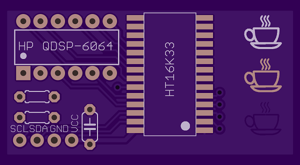
There are two main types of test points used on a printed circuit board. The first is an easily accessible point for a technician to access with hand-held testing equipment. To help with this, these points often have a post soldered into them for clipping on a test lead. These test points will be marked with a reference designator and usually the name of the net in silkscreen for easy reference, such as “GND.”
Do you know the definition of text points in PCB? If you are looking for more professional information about text points in PCB, please check and read the content below for more information.

Why we have to process text points in PCB?
Just mention the word “test” and most people will feel their heart skip a terrifying beat. There is something very intimidating about taking a test that seems to be instilled in us from our first days of elementary school. As everyone knows, though, testing is a very important part of life. You wouldn’t want to fly on a plane with a pilot who failed her flight examination, and the idea of a surgeon who didn’t pass his basic anatomy class brandishing a scalpel should scare everyone.
The circuit boards we design also have some testing to go through; and, in their case, the testing will determine how well they have been manufactured. In order for this testing to happen, the board must be prepared with specific elements that a test probe can access. These elements are called test points and their inclusion on PCB designs is very important. Let’s take a few minutes here to talk about the PCB test point and why it is so important to the success of the completed circuit board.
Which signals should have test points?
· Power supply rails
· Ground
· Programming connections
· JTAG ports
· Serial communications busses
· Reset lines
· UARTs
· Programmable references
· Interrupt lines
Other signals can be of use to the development and production teams. This is especially important where a key signal is routed between BGA, QFN or LGA devices. As without planning there would be no access to the signal.
Are test points useful for quality control?
Quality control gold for the production line
The real value comes in the production environment where you can use test points for quality control or for programming, setup, or calibration. Repeatable automation of these tasks can speed up the process, reduce costs and de-skill engineering led tasks to allow non-technical staff to reliably use.
Do they speed things up?
Having test points can speed up development and more importantly provide you with quality control reassurance. It also gives you the ability to automate set up test calibration. Vitally it is also traceable.
Can test points be used for traceability?
Using traceability to check a fault’s origin using historic data
Test results can be linked to individual boards and products using bar codes and label printers. Each board can be scanned to access its test record. Testing with historic evidence is very useful if problems emerge later if the right measurements have been recorded. You can look at test result trends to better understand if an issue is batch related, supply chain related or has other causes such as a bill of materials change or firmware update.
Sometimes knowing something is going to fail now is far better than getting an instant pass, why? Because of the time and money it saves.
During our careers as engineering in product development we have sadly often spoken with product owners who have no sub-assembly testing in place. This means that the full product needs to be assembled before any faults can be observed. This leads to costly and time-consuming reworks.

Why Test Points Are Important for PCB Manufacturing?
Automated testing is essential for verifying the manufacturing of printed circuit boards. While a bare board test checks that the fabricated board has good connectivity, ICT and flying probe tests will verify the board assembly and solder connections. Here is how ICT and flying probe testing accomplish that:
In-Circuit Test (ICT)
ICT is a system that uses a test fixture that is prepared exclusively for a specific circuit board design as well as accompanying software that will be run on the test system. The fixture and software are created using the test point locations and other design data generated by the CAD database, and a probe will be used for each net on the design. While the main purpose of ICT is to verify the assembly of the board by testing each net for a good connection to its associated part pin, it can also be used to test the functionality of the board.
ICT test fixtures and software are expensive and time-consuming to develop. The test fixtures are complex with thousands of probes in them and changes to a fixture for board revisions can also be very expensive. Once developed, though, the in-circuit test will test large amounts of circuit boards very quickly. For mass production, the benefits of speed and functional testing quickly offset the development time and costs of ICT.
Flying Probe Testing
This system is also designed to verify the integrity of an assembled circuit board, but it does this very differently than ICT. Instead of a test fixture, there are only two to six probes that fly around accessing each test point on the board. Without the need to build an expensive test fixture, the flying probe system can be set up very quickly and inexpensively. Also, any changes to the board that require changes to the test system can be easily reprogrammed.
Industry Category


