PCB interconnect
By:PCBBUY 07/23/2021 17:05

As a part of the whole machine, a printed circuit board generally cannot constitute an electronic product, and there must be a problem of external connection. Electrical connections are required between circuit boards, circuit boards and off-board components, printed circuit boards and equipment panels. The selection of the best combination of reliability, process and economy is one of the important contents of pcb board design. There are many ways to connect externally, and you have to choose flexibly according to different characteristics.
In this passage, we will focus on the PCB interconnect. Please check and read the content we prepare for more professional knowledge.
What are the methods of PCB interconnect?
Soldering
The advantages of this interconnection method are simple, low cost, high reliability, and can avoid the faults caused by poor contact. Disadvantages are not easy to change or not very convenient for maintenance. This method is generally applicable to components with fewer external leads.
1. Soldering of PCB Leads:
This method does not require any connector clip, as long as soldering directly and firmly the external interconnection points on PCB with the PCB components or other components outside, such as the speaker in the radio, battery box and so on.
The points needing attention when soldering interconnections on PCB are as follows:
· Soldering pads for leads shall be placed as far as possible on the edge of PCBs and arranged in the same size to facilitate soldering and maintenance.
· In order to improve the mechanical strength of the wire connection, it’s necessary to avoid damage to the solder pads or printed leads caused by the leads being pulled. In addition, the holes should be drilled near the solder joints on the PCBs to allow the leads to pass through the holes on the solder side of the PCBs, and then insert the holes of solder pads from the component side for soldering.
· Arrange or tie the leads neatly, and fix them with PCB through line-card or other fasteners to prevent the leads from breaking due to movement.
2. Soldering of PCB Flexible Flat Cable:
The two PCBs are connected by flexible flat cables, which is reliable and not prone to connection errors, and the relative position between the two PCBs is not limited. Directly soldering between PCBs, are often used to connect the two PCBs at an angle of 90 degrees. After connecting, it becomes an integral PCB part.

Connector Clip
In more complex instruments and equipment, the interconnection methods of connector clip is often used. This "building block" structure not only ensures the quality of mass production, but also reduces the cost of the system and facilitates debugging and maintenance. When device fails, maintenance personnel don’t need to check the component level. That is, in order to check the cause of the failure, until check to the specific component. This work will take quite a long time.), as long as maintenance personnel judge which PCB is abnormal, they can immediately replace that PCB, which cannot only eliminate faults in the shortest time, but shorten the downtime. Thus, it can improve the utilization rate of the device. In addition, the replaced PCB can be repaired in plenty of time and used as spare parts after repair.
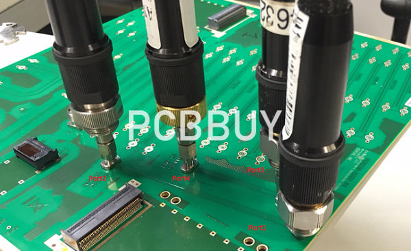
1. PCB Socket Interconnection:
This interconnection is often used in more complex instruments and devices. This method makes the printed plug from the PCB edge, and the plug part is designed according to the size of the socket, the interconnection points, the contact distance, the location of the positioning holes and so on, so as to make it match with the special PCB socket.
When manufacturing PCB, the plug part needs to be gold-plated to improve wear resistance and reduce contact resistance, which has the simple assembly, great interchangeability, good maintenance performance, and is suitable for standardized mass production. The disadvantage of this method is that the cost of PCB is increased, and the requirements of PCB manufacturing precision and process are higher. In addition, its reliability is poor. For example, it often lead to poor contact because the plug part is oxidized or socket spring aging. In order to improve the reliability of external interconnection, the same outgoing line is often drawn out in parallel through the contacts on the same side or both sides of PCB.
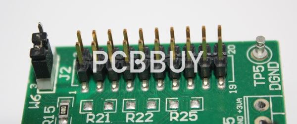
2. Standard Pin Interconnection:
This method can be used for PCB external interconnection, especially in small instruments commonly used pin connection. Two PCBs are connected by a standard pin, and they are generally parallel or vertical as it is benefit for the mass production.
Industry Category


