Crosstalk PCB
By:PCBBUY 08/14/2021 09:25

Crosstalk is the disturbance caused by energy coupling from one PCB trace to another even if they are not in contact. It happens due to the interaction of electric (capacitive coupling) and magnetic fields (inductive coupling). The magnetic field generates mutual inductance, and the electric field generates mutual capacitance between the traces in the vicinity. Mutual inductance is responsible for inducing current on the adjacent (victim) line, which is opposite of the current in the aggressor line. And the capacitor formed due to mutual capacitance will pass the current in both directions on the victim line.
In this passage, we will focus on the topic and if you want to learn more professional information check and read the content below.
What are the types of crosstalk in PCB?
Based on trace routing and location of the disturbance on the aggressor and victim lines, crosstalk can be classified as:
1. Capacitive crosstalk: It arises due to the traces that run on top or near to each other, producing a capacitive effect.
2. Inductive crosstalk: It generates due to magnetic field interaction between traces running parallelly over a long distance.
Inductive crosstalk is of two types: forward and backward. Forward is the noise/disturbance observed at the farthest end from the driver on the driven line, while backward crosstalk is the disturbance observed at the nearest end on the victim line.
Near-end crosstalk (NEXT): It is measured at the transmitter end of the transmission line or a cable.
Far-end crosstalk (FEXT): It is measured at the receiver end of the transmission line or a cable.
NEXT and FEXT are measured with respect to the port to which the stimulus is applied. It can occur anywhere along a line, whether it is a dual conductor or single-ended.
Note: The NEXT value is expressed in decibels (dB) and varies with the frequency of transmission. A higher dB of NEXT means less interference.
3. Power sum near-end crosstalk (PSNEXT): It is the sum of the NEXT of three aggressor pairs as it impacts the fourth victim pair. PSNEXT gives total crosstalks from all the adjacent pairs and involves measuring all pair-to-pair groupings relative to power.
4. Equal level far-end crosstalk (ELFEXT): It is the measurement of the FEXT that involves attenuation compensation.
5. Alien crosstalk: It gives the measurement of crosstalk in PCBs for telecom systems. Above mentioned types are the ways of measuring or quantifying crosstalk in a system. Crosstalk can also be measured using a TDR. For more details, read our post on how TDR impedance measurements work.

How to measure crosstalk?
Crosstalk is generally specified as a percentage of the signal that appears on the victim line, relative to the aggressor line. It can also be expressed in terms of dB below the driven line level. NEXT varies with the frequency of the transmission since higher frequencies create more interference. The higher the dB value, the less crosstalk is received by the disturbed link/channel. FEXT is calculated from the crosstalk elements of the system S-parameters.
The formula for crosstalk is given by: 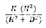
Where:
K = A constant whose value always remains less than 1 and depends upon the rise time of the circuit and the length of the traces experiencing crosstalk.
H2 = It is the product of the height of the parallel traces.
D2 = It is the product of the direct distance between the centerline of the traces.
The above equation clearly shows that crosstalk can be minimized by reducing H and maximizing D.
Crosstalk in dB is given by: 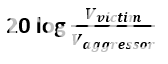
Where, V victim is the voltage on the victim line and Vaggressor is the voltage on the aggressor line.
Factors affecting the magnitude of crosstalk
1. Degree of coupling between aggressor and victim lines
2. The distance up to which coupling occurs
3. Effectiveness of the type of termination used

What are the causes of crosstalk?
· Capacitive and inductive coupling: Capacitive coupling is due to parasitic capacitance and inductive coupling occurs due to mutual inductance.
· Difference in propagation velocity: It can be avoided by trace length matching and propagation delay matching.
· PCB vias: PCB vias with stubs create reflections, thus ringing which generates crosstalk. One way to avoid this is to back drill the vias.
· Increased data rates: With increased data rate, the rise time increases as well. According to Faraday’s law, with an increase in rise time, the crosstalk will also increase. One way to reduce crosstalk between such signals is to increase the spacing between the traces.
· Board size: As the PCB board size increases, the trace lengths also increase, and these traces behave as antennas. So, it is important to keep the trace lengths as minimum as possible.
Industry Category


