Metal core PCB
By:PCBBUY 08/04/2021 18:09

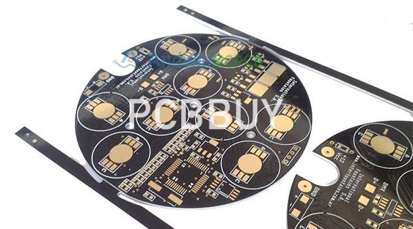
A metal core printed circuit board (MCPCB) also known as thermal PCB, incorporates a metal material as its base as opposed to the traditional FR4, for the heat spreader fragment of the board. Heat builds up due to some electronic components during the operation of the board. The purpose of the metal is to divert this heat away from critical board components and towards less crucial areas such as the metal heatsink backing or metallic core. Hence, these PCBs are apt for thermal management.
In a multilayer MCPCB, the layers will be evenly distributed on each side of the metal core. For instance, in a 12-layer board, the metal core will be at the center with 6 layers on the top and 6 layers at the bottom. MCPCBs are also referred to as insulated metallic substrate (IMS), insulated metal PCBs (IMPCB), thermal clad PCBs, and metal-clad PCBs. In this article, we will be using the abbreviation MCPCB to avoid ambiguity.
Why to choose metal core PCB?
Accumulation of too much heat in printed circuit boards lead to malfunctions in the devices. Electronic devices that generate a considerable amount of heat cannot always be cooled using conventional fans. Conductive cooling through metal core boards is an ideal option. In conductive cooling, the heat is transferred from one hot part to a cooler part by direct contact. This works well since heat constantly seeks to move to any object or medium that is cooler.
What are the applications of metal core PCB?
MCPCBs are most widely found in LED lighting technologies. Some of the popular applications are:
· LED – Backlight unit, general lighting
· Automotive – motor control for Electric/Hybrid cars
· Motor drives
· Solid-state relays
· Power supply devices – voltage regulators, switching regulators, DC-DC Converters
· Solar panels, Photovoltaic Cells
· Motion control
What are the advantages of metal core PCB?
These boards possess the ability to integrate a dielectric polymer layer with high thermal conductivity for lower thermal resistance.
· The higher the conductivity of the material, the faster the heat transfer.
· The metal boards can be etched to control heat flow away from components
· Boards with aluminum, tend to be lighter in weight than ceramics.
· Metal substrates are long-lasting and are more conductive than epoxy products.
· Metals are non-toxic and are recyclable.
· Implemented in high vibration applications. The components don’t fall off since the core reduces the vibration.

What are the types of metal bases utilized in metal core PCB?
Aluminum substrate – The aluminum printed circuit boards offer good heat dissipation and heat transferring ability. Since they are light in weight, the aluminum core PCBs find their purpose in LED lighting, audio frequency apparatus, and communication electronic equipment.
Here, the thickness of the core ranges between 40 mils and 120 mils, with 40 mils and 60 mils being the most commonly used. Characteristics of the MCPCB with Aluminum substrate are as given below:
· Aluminum thickness: 2mm to 8mm
· Thermal conductivity: 5W/(mK) to 2.0W/(mK) (Watts per meter Kelvin)
· Peeling strength: >9lb/in
· Solder resistance: SF: 288℃, >180 sec.
· Breakdown voltage: >3000V
· Dielectric loss angle: 0.03
· Flammability: UL 94V-0
· Panel size: 18” x 24”
Copper base (copper core or heavy copper) – The copper core boards feature better performance than aluminum. But customers generally choose aluminum since copper is relatively expensive. Also, copper cores are heavier and involve a tough machining process. Copper also corrodes easier than aluminum.
Plated through holes in MCPCB
A major factor to keep in mind during the design process of an MCPCB is to minimize the use of plated through-hole components. Instead, implement SMT components. Since the bottom layer is a metal, PTH or NPTH with conductive component leads inserted to it will lead to a short. If PTHs are implemented, then do remember to isolate the metal from the through-hole. To achieve this, the metal core is drilled approximately 40 mils to 50 mils larger than the plated through-hole. Later, these holes are filled with non-conductive epoxy filler and then pressed.
After pressing the metal core, the remaining filler compounds are removed from the surface. Following this, the boards are prepared for the lamination with the inner layer cores. Right after lamination, the plated through holes are drilled and the rest of the process follows as per the standard manufacturing protocol.
Unlike the standard LED PCBs which require vias under the components for heat dissipation, the MCPCBs eliminate the necessity of these kinds of vias since the metal core performs the heat dissipation. Hence, this makes the work easier for the manufacturers as the drilling process is kept minimal. After this process, if it’s a 1-layer MCPCB, the electroless plating process is bypassed and proceeds straight to circuit imaging. Hereafter, the metal core boards follow the same procedure that a standard FR4 board would follow.
Industry Category


