Stray capacitance in PCB
By:PCBBUY 07/22/2021 16:56

Capacitance is the property of a set of conductors or an electric conductor measured accurately by the quantity of separated electric charge (Geaghan, 2013). Capacitance is often stored on it per unit change or fluctuation in electrical potential. It is worth mentioning that capacitance also indicates related storage of electrical energy.
Stray capacitance is a type of capacitance; unwanted, excess, or preferably unavoidable capacitance induced in a variety of electronic components because of their parallel alignment is typically known as stray capacitance.
In this passage, we are going to talk about stray capacitance. Please check and read the content we prepare below.
What are the effects of stray capacitance in PCB?
In high voltage and high-frequency systems, conductors do not need another conductor to produce capacitance between them. It is because it is induced merely by interaction with the environment. Note that in Printed Circuit Boards (PCB), this often results in plenty of unwanted or unnecessary capacitance that may impact the performance of a system.
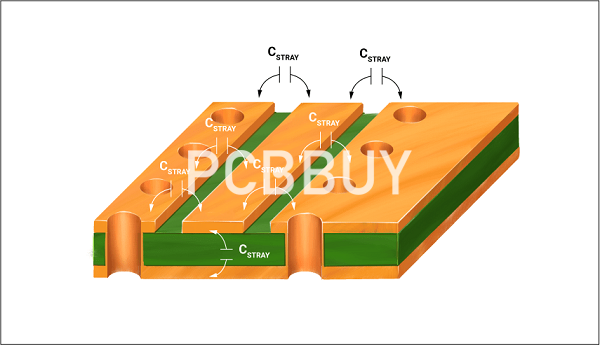
Electronic design automation computerized programs that are used in designing most commercial printed circuit boards could calculate the stray capacitance and other parasitic impacts of both circuit board traces and components and tend to include them invaluable simulations of circuit operation. This is known as parasitic extraction (Kao, Lo, Singh, & Basel, 2001). Using the figure below, we can easily calculate the stray capacitance for a conductor in any PCB substrate. Note that this capacitance may theoretically be used in a variety of places that need small discrete capacitors, but it is, in most cases, an inefficient way.
It is important to remember that in a majority of higher frequency amplifiers, the stray capacitance may combine easily with some stray inductance, like component leads, to form various resonant circuits, which can also lead to a phenomenon called parasitic oscillations.
In almost all inductors, the parasitic capacitance may resonate with the inductance at some high frequency to make an inductor self-resonant; this is known as the self-resonant frequency. Above this specific frequency, the inductor has capacitive reactance.

Designers of electric circuits try their best to minimize or eliminate stray capacitances, if possible. They often do this by carefully keeping all of the leads of electronic parts concise and grouping these parts in a way that eliminates capacitive coupling. The stray capacitance of a load circuit attached firmly to the output in op-amps may lower their bandwidth.
A majority of high-frequency electric circuits need specialized design techniques like careful separation of components and wires, guard rings, power planes, ground planes, shielding between output and input, termination of strip lines, and lines to minimize the impacts of unwanted capacitance.
What are the trends of stray capacitance in PCB?
Three main factors in capacitor construction determine the number of stray capacitances created. All these factors affect stray capacitance by impacting the amount of electric field flux that would develop for a specific amount of electric field force (this is the voltage between any two boards)
Board Spacing
Keeping all other factors constant, more spacing between boards gives less stray capacitance; on the other hand, closer board spacing can produce more stray capacitances. Closer board spacing can result in a higher field force, And for any particular voltage applied to the two boards, this results in a relatively high field flux (charge accumulated on both scales).
Board Area
All other variables constant; more board area provides more stray capacitance while less board area generates less stray capacitance.
Dielectric Material
Keeping all other variables constant, the higher permittivity of a dielectric material produces greater stray capacitance, while less permittivity of a dielectric material produces less stray capacitance.
Relative permittivity indicates the permittivity of materials; it is close to a vacuum (pure) (Rubin and Ho, 2018). For instance, glass with a relative permittivity of seven has seven times the standard permittivity of vacuum. It hence will lead to the production of an electric field flux that is seven times stronger compared to that of a pure vacuum, when all other variables are equal.
In this chapter, we have discussed the different trends in stray capacitances and the factors that have an impact on stray capacitance. In the next section, we will consider some ways to lower stray capacitance.
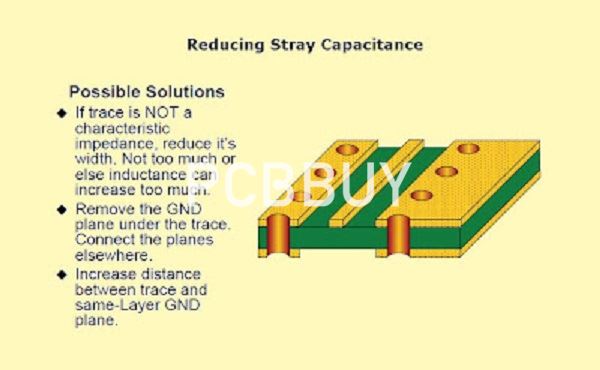
How to reduce stray capacitance?
In many applications, the stray capacitance between multiple signal lines could deplete or impact the whole design. It is worth mentioning that at lower frequencies, the stray capacitance can often be ignored. However, at high frequencies, it could be the main problem in electric circuits. We can control stray capacitances at the layout level.

Stray capacitances often arise due to an electrical coupling generated between a signal line and the other signal line or the substrate and a signal line. It is worth mentioning that in many designs, it can become essential to lower stray capacitance of a specific net regarding other signals. These are a few of the most effective methods for decreasing stray capacitance:
1. Increasing the spacing between the various nets from the specific set is crucial (for which stray capacitance is quite important).
2. I am using higher metals for those nets where the stray capacitance is vital.
3. Avoiding excess parallel routing of metals
4. Place another reference signal between various networks that require low stray capacitance (where the stray capacitance is not essential). It is called shielding.
This chapter discusses four ways you can reduce stray capacitance. In the next section, we will discuss stray capacitance in transformers.
Industry Category


