What is the Standard of Aluminum PCB Thermal Conductivity?
By:PCBBUY 03/31/2025 15:24
Introduction
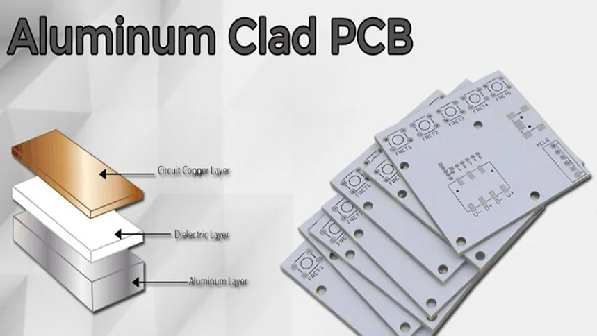
Aluminum PCBs (Metal Core Printed Circuit Boards, MCPCBs) are widely used in high-power LED lighting, power electronics, and automotive systems due to their superior thermal management capabilities. Unlike traditional FR4 PCBs, aluminum PCBs utilize a metal base layer (typically aluminum) to dissipate heat efficiently.
The*thermal conductivity of an aluminum PCB is its most critical performance parameter, directly affecting heat dissipation, component lifespan, and overall system reliability. This 5000+ word technical guide examines the standards, measurement methods, material comparisons, and design considerations for aluminum PCB thermal conductivity, supported by industry data, test standards, and material science principles.
1. Fundamentals of Aluminum PCB Thermal Conductivity
1.1 What is Thermal Conductivity?
Thermal conductivity (k, measured in W/m·K) defines a material's ability to conduct heat. In aluminum PCBs, heat generated by components (e.g., LEDs, power transistors) transfers through the dielectric layer to the aluminum base, which dissipates it into the environment.
1.2 Why is Aluminum Used in PCBs?
High thermal conductivity (200-230 W/m·K for pure aluminum)
Lightweight and cost-effective compared to copper
Excellent mechanical stability
Comparison of Metal Substrates
|
Metal |
Thermal Conductivity (W/m·K) |
Cost |
Common Applications |
|
Aluminum |
200-230 |
Low |
LED lighting, power supplies |
|
Copper |
380-400 |
High |
High-power RF/military |
|
Steel |
15-50 |
Very low |
Low-cost consumer electronics |
2. Industry Standards for Aluminum PCB Thermal Conductivity
2.1 IPC & ASTM Standards
IPC-2221 (Generic PCB Design Standard)
IPC-6012 (Qualification for Rigid PCBs)
ASTM D5470 (Standard Test Method for Thermal Conductivity of Plastics)
2.2 Thermal Conductivity Classifications
Aluminum PCBs are categorized by their dielectric layer’s thermal performance:
|
Dielectric Type |
Thermal Conductivity (W/m·K) |
Typical Applications |
|
Standard Epoxy |
0.8 - 1.5 |
Low-power LED boards |
|
High-Performance Ceramic-Filled |
2.0 - 6.0 |
Power converters, automotive |
|
Ultra-High Conductivity |
6.0 - 12.0 |
Aerospace, military electronics |
Note: The aluminum base itself typically has **200+ W/m·K**, but the dielectric layer is the bottleneck.
3. Measuring Thermal Conductivity in Aluminum PCBs
3.1 Common Test Methods
A. ASTM D5470 (Modified for PCBs)
Measures heat flow through the dielectric layer.
Uses a heat flux sensor and controlled temperature gradient.
B. Laser Flash Analysis (ASTM E1461)
A laser pulse heats one side, and an IR detector measures heat diffusion.
Best for bulk material testing (e.g., aluminum core).
Comparison of Test Methods
|
Method |
Accuracy |
Speed |
Best For |
|
ASTM D5470 |
±5% |
Slow |
Dielectric layer testing |
|
Laser Flash |
±3% |
Fast |
Metal core evaluation |
|
Thermal Imaging |
±10% |
Medium |
In-situ PCB inspection |
3.2 Real-World Test Data
|
PCB Type |
Dielectric k (W/m·K) |
Aluminum Core k (W/m·K) |
|
Standard LED MCPCB |
1.2 |
220 |
|
Automotive Power PCB |
3.5 |
225 |
|
High-Frequency RF PCB |
8.0 |
210 |
4. Factors Affecting Thermal Performance
4.1 Dielectric Layer Thickness
Thinner dielectric = better heat transfer but reduced electrical insulation.
Typical Thickness Range: 50µm - 150µm.
Impact of Dielectric Thickness on Thermal Resistance
|
Thickness (µm) |
Thermal Resistance (°C/W) |
|
50 |
0.25 |
|
100 |
0.50 |
|
150 |
0.75 |
Assumes dielectric k = 2.0 W/m·K*
4.2 Aluminum Purity & Alloys
6061-T6 Aluminum (Most Common):
k = **167 W/m·K
Good balance of cost and performance.
Pure Aluminum (1100):
k = 220 W/m·K
Used in high-end applications.
5. Design Guidelines for Optimal Thermal Conductivity
5.1 Copper Thickness & Trace Layout
Thicker copper (2oz+) improves heat spreading.
Avoid isolated thermal pads (use thermal vias for multilayer designs).
5.2 Thermal Interface Materials (TIMs)
Thermal paste/pads between PCB and heatsink reduce interfacial resistance.
Recommended TIM Conductivity: >5 W/m·K.
5.3 Industry Best Practices
For LED PCBs: Use k ≥ 2.0 W/m·K dielectric to prevent lumen depreciation.
For Power Electronics: k ≥ 6.0 W/m·K for MOSFET/IGBT cooling.
6. Case Study: Thermal Conductivity in LED Street Lights
Problem: LED junction temperature exceeded 120°C, reducing lifespan.
Solution: Upgraded from 1.2 W/m·K to 3.0 W/m·K dielectric.
Result: Temperature dropped to 85°C, improving MTBF by 3x
Conclusion
The thermal conductivity of aluminum PCBs is governed by dielectric material properties, metal core selection, and manufacturing quality. Designers must balance thermal performance, cost, and reliability while adhering to IPC and ASTM standards
For high-power applications, ceramic-filled dielectrics (k > 6.0 W/m·K) are recommended, while standard LED boards can use 1.5 - 3.0 W/m·K materials.
References
1. IPC-2221 – Generic Standard on Printed Board Design
2. ASTM D5470 – Thermal Conductivity of Electrical Insulating Materials
3. Bergquist Technical White Papers – MCPCB Thermal Performance
4. "Advanced Thermal Management Materials" – C.P. Wong
5. IEEE Transactions on Components, Packaging, and Manufacturing Technology
Industry Category


