What is the basic definition of THT in PCB?
By:PCBBUY 05/31/2023 15:16
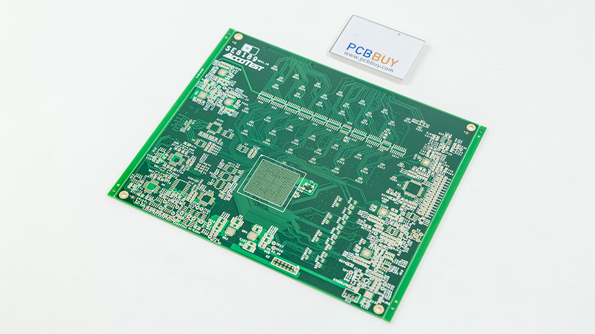
Through hole technology involves inserting components with tails or leads into holes drilled in the PCB. These components will be described as through board components. The leads can then be soldered onto pads or lands on the underside of the board, usually with a wave solder process (but also by hand).
Are you going to learn more professional knowledge about THT PCB? If you are searching for more information of THT PCB, please check and read the content below in this passage.
What is the basic definition of THT in PCB?
Before the invention of the SMT ( Surface Mount Technology) all components were assembled to the PCB with leads going through component holes in the board. This technology dominated the industry till the end of the eighties. Today most components placed are SMT components. You could think that THT (Through Hole Technology) is now outdated and not used anymore, as SMT is more efficient, cost effective and adapted to denser boards. However THT offers specific benefits that keep it relevant.
The bonds created between THT components and the board are far stronger than SMT bonds, making THT the ideal choice for components that will undergo mechanical and environmental stress or high heat. In case of prototyping THT components are also easy to change, making them perfect for testing and hobby users. There are disadvantages too. Through hole components are much bigger and the component itself is on one side but the solder joint is on the other side, so using space on both sides. THT also restricts the available routing area on inner layers since the holes must be drilled through all the PCB layers.
What are the technologies of THT in PCB?
The THT assembly process is not automated, depends on the skills of the operators, is thus less reliable and more expensive than SMT. Before placing the TH components we first cut the leads to the required size. Some components need to be placed at a certain distance of the board. We use ‘spacers’ from plastic or metal to place the components at the desired height. The spacers are fixed by soldering, screwing or snap-fitting.
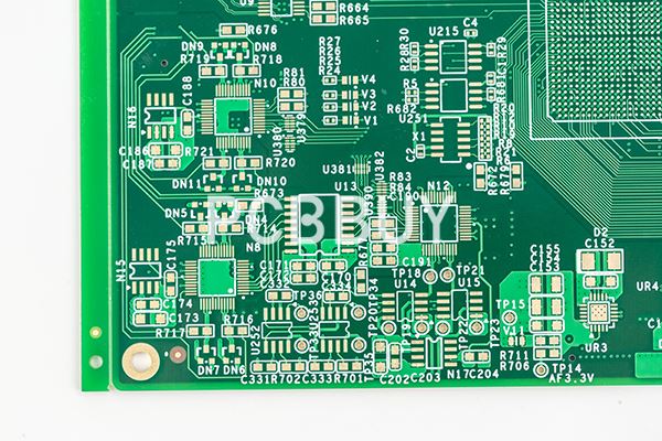
Through hole is one of essential parts for multi-layer PCB design. A through hole is composed by three parts: via, pad and isolation area of power plane, which can be demonstrated in the following image. THT is obtained by plating a layer of metal on hole wall in a way of chemical deposit so that copper foil from each internal layer or plane of a circuit board can be connected with each other. Two sides of through holes are generated in the shape of an ordinary pad, both of which can be directly connected with tracing on top and bottom layers and can be maintained unconnected as well. A through hole plays a role in electrical connection, fixation and positioning components.
As far as THT is concerned, through holes are generally classified into through-hole via, blind via and buried via:
Through-hole via goes through all layers of a circuit board, applicable for internal interconnection or playing a role as a positioning hole. Since through-hole vias are accessible in technology with a low cost, they are widely applied by most PCBs. Blind via refers to the hole responsible for the connection between surface traces and internal traces below with certain depth. Ratio between via depth and via diameter usually doesn't exceed a certain value. Buried via refers to connecting via located in internal layers, which cannot be seen from the appearance of a PCB board because it fails to be expanded to the surface of circuit board.
What are the differences of THT VS SMT?
THT and SMT are two reliable mounting technologies in PCB assembly. However, SMT is more reliable and more common. There are differences between these two technologies. While SMT replaces THT, THT is still being used in PCB assembly.
THT inserts electronic component leads into drilled holes on a circuit board. Most times, manufacturers carry out this technique manually. SMT technology doesn’t require as many drilled holes as THT does. The use of pick and place machines in SMT makes the technique much easier for manufacturers.
SMT doesn’t require leads and can be directly mounted on the circuit board. Whereas, THT requires lead wires that manufacturers place in drilled holes. SMT requires advanced production and design skills compared to THT.
THT vs SMT In terms of manufacturing costs, THT involves a higher cost of manufacturing than SMT. However; capital investment for automated equipment is higher than that of THT. THT is ideal for certain applications. Through hole boards are ideal at the prototype stages of a project. For a through hole board, manufacturers don’t need to produce a new solder stencil anytime the circuit board goes through a revision change.
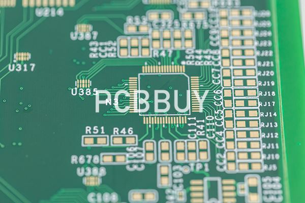
THT vs SMT via through hole technology. This technology is ideal for the manufacturing of bulky components. SMT is ideal for higher circuit speeds since it features fewer holes. Unlike THT, SMT allows assembly automation which is ideal for the production of higher volumes at reduced costs.
SMT provides more board space during assembly, unlike THT which uses up the board space. THT helps manufacturers to check mechanical problems during validation. The manufacturer can fix this problem during redesign without any assembly difficulties. However, in SMT, this is difficult to fix. This is because warp and twist is easier to fix on a manually-assembled PCB.
Industry Category


