PCB Panelization Mouse Bites vs V-Score: Best Practices for PCB Design and Manufacturing
By:PCBBUY 10/29/2026 15:09
Introduction
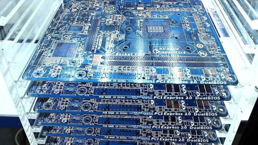
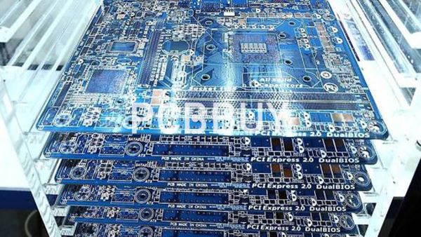
PCB panelization combines multiple printed circuit boards into a single array, making handling, automated assembly, inspection, and production more efficient. Two commonly used separation methods are mouse bites (perforated breakaway tabs) and V-scoring (V-cut). Although both hold individual boards together during manufacturing and assembly, they differ in outline flexibility, edge quality, mechanical stress, and processing cost.
Choosing the right method early in the design stage can reduce depanelization damage, improve assembly yield, and avoid unnecessary rework. For applications such as automotive electronics, industrial control, power supplies, energy storage, and embodied robotics, panelization should be evaluated as part of the complete manufacturing process—not simply as a way to fit more boards onto one panel.
1. What Are Mouse Bites and V-Scoring?
Mouse Bites: Flexible Panelization for Irregular PCB Shapes
Mouse bites are rows of small drilled holes placed along narrow breakaway tabs. Routing around these tabs separates most of the board outline while leaving selected connections to hold each PCB in the panel.
This approach is suitable for irregular outlines, curved edges, and designs that cannot be separated along continuous straight lines. However, breaking the tabs can leave small protrusions or rough edges that may require additional finishing.
V-Scoring: Efficient Separation Along Straight Lines
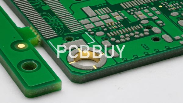
V-scoring, also called V-cutting, uses V-shaped grooves on the top and bottom surfaces of a PCB panel. A thin section of material remains between the grooves, allowing the individual boards to be separated after assembly.
V-scoring is generally well suited to rectangular PCBs with straight, continuous separation lines. It supports close board-to-board arrangement and can reduce routing requirements, but it offers less flexibility for complex outlines and may expose assemblies to mechanical stress during separation.
2. Mouse Bites vs. V-Score: Key Differences
|
Design consideration |
Mouse bites |
V-scoring |
|
PCB outline |
Suitable for irregular or curved outlines |
Best for straight, continuous edges |
|
Panel layout |
Requires routed gaps and connecting tabs |
Often allows boards to sit edge-to-edge |
|
Edge condition |
May leave rough tabs or small protrusions |
Usually produces a more uniform edge along the score line |
|
Mechanical stress |
Concentrated around breakaway tabs |
Bending stress occurs along the scored line |
|
Component clearance |
Keep sensitive parts away from tabs and perforations |
Keep components and copper away from the score line |
|
Manufacturing cost |
Routing and perforation add processing requirements |
Often economical for suitable rectangular arrays |
|
Common applications |
Compact controllers, irregular sensor boards, robot electronics |
Rectangular control boards, power boards, high-volume assemblies |
Neither method is universally superior. The best choice depends on board geometry, thickness, copper distribution, component placement, assembly equipment, and the required edge condition.
3. PCB Panelization Mouse Bites vs V-Score Best Practices
3.1 Select the Separation Method Before Layout Is Finalized
Do not leave panelization decisions until the fabrication stage. Define the board outline, panel arrangement, and separation method early, particularly when components are close to the PCB edge.
For rectangular boards with continuous straight boundaries, V-scoring is often a practical first choice. For irregular outlines, routed cutouts, or boards requiring selected connection points, mouse bites are usually more appropriate. A mixed panel using both methods may also be possible, subject to manufacturing review.
3.2 Design Mouse-Bite Tabs for Controlled Breakaway
Mouse-bite geometry should balance two competing requirements: the tabs must remain strong enough to withstand fabrication, shipping, solder paste printing, component placement, and reflow, yet weak enough to separate without damaging the PCB.
Best practices include:
-
Place perforated tabs at mechanically suitable locations rather than beside fragile components or critical circuitry.
-
Define hole diameter, spacing, tab width, and routing path according to the PCB manufacturer's recommendations.
-
Keep copper, plated features, and sensitive components away from the perforation and breakaway zone.
-
Consider whether residual material at the edge is acceptable or whether secondary finishing is required.
-
Avoid placing all tabs in a way that concentrates separation force on one small region.
Hole patterns should not be copied blindly from another design. The appropriate geometry depends on board thickness, material, tab dimensions, and the intended separation method.
3.3 Control V-Score Depth and Edge Clearance
V-scoring requires careful control of groove depth and alignment. If too much material is removed, the panel may become fragile during assembly. If too much material remains, separation may require excessive force and increase the risk of cracking or component damage.
Designers should:
-
Specify the score lines clearly in the mechanical drawing or fabrication notes.
-
Confirm groove depth, residual thickness, score alignment, and acceptable tolerances with the manufacturer.
-
Maintain suitable clearance between score lines and copper features.
-
Keep components—especially mechanically sensitive components such as MLCCs—away from the separation zone.
-
Check whether connectors, mounting features, or components extending beyond the board edge conflict with the score line.
The residual web and score geometry should follow the manufacturer's process capability and the product's mechanical requirements rather than a universal assumed value.
3.4 Consider SMT Assembly and Final Product Requirements
Panelization must support the entire production flow. Small or unusually shaped PCBs may need process rails, tooling holes, and global or local fiducials to improve handling and optical alignment on SMT equipment.
For automotive controllers, industrial control systems, power conversion boards, and energy-storage electronics, mechanical damage caused during separation can become a reliability concern. Robot control and sensor boards may also have connectors or components close to the outline, making clearance planning particularly important.
If the final product requires a highly controlled edge profile, do not assume that either mouse bites or V-scoring will meet the requirement without further evaluation. State the edge-quality criteria before production.
4. Manufacturing Review and Quality Control at PCBBUY
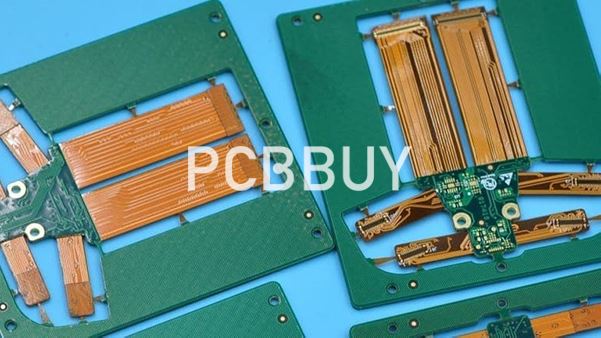
PCBBUY provides PCB manufacturing services covering multilayer boards and supports panelization processes including V-CUT and routed outlines. Its published manufacturing capability lists PCB production from 1 to 26 layers and a maximum board or panel dimension of up to 1000 × 600 mm, subject to layer count and the applicable production configuration. The actual permissible panel size and V-CUT direction depend on the specific stack-up and process limits.
For a new panelized design, PCBBUY's engineering review should confirm:
-
Panel feasibility: Verify panel dimensions, layer count, board thickness, and the selected separation method.
-
Mechanical design: Check routing paths, mouse-bite tabs, V-score locations, edge clearances, rails, and tooling features.
-
Assembly compatibility: Confirm fiducial placement, component clearance, and handling requirements for the intended SMT process.
-
Inspection and testing: Apply the relevant visual, dimensional, and electrical checks to the agreed product specification.
-
Packaging and shipment: Confirm whether the order should be delivered as a complete panel or as separated individual boards, and protect the panels against bending and edge damage during transit.
PCBBUY's published manufacturing flow includes PCB processing, routing/V-CUT, finished-board inspection, electrical testing, final quality inspection, and packaging. The exact inspection plan and acceptance limits should be agreed according to the drawing, order specifications, and applicable IPC requirements.
For projects supported by PCBBUY, these engineering checks are relevant to automotive electronics, industrial controllers, power supplies, electricity and energy-storage equipment, new-energy systems, and embodied-robot control electronics. The recommended panel structure should be selected around the product's mechanical and assembly needs rather than forcing every design into one standard method.

5. Shipment Acceptance Checklist
|
Inspection item |
What to verify before shipment |
|
Panel dimensions |
Match the approved fabrication drawing and order specification |
|
Separation features |
V-score or routed-tab positions match the approved design |
|
Edge quality |
No unacceptable cracks, delamination, copper exposure, or edge damage |
|
Board integrity |
No visible damage caused by routing, scoring, or handling |
|
Electrical performance |
Required continuity, isolation, and other specified electrical tests pass |
|
Packaging |
Panels are adequately supported and protected against bending, impact, and moisture where applicable |
Acceptance criteria should be documented before production. If the customer requires a particular edge roughness, residual tab height, or depanelization stress limit, it should be explicitly stated and reviewed with the manufacturer.
Conclusion
The practical choice in PCB panelization mouse bites vs V-score best practices comes down to the board outline, separation stress, component placement, edge requirements, and production workflow. V-scoring is often efficient for straight-edged rectangular boards, while mouse bites provide greater flexibility for irregular shapes and routed outlines.
A successful panelization design combines manufacturable geometry, adequate component clearance, controlled separation, and clearly defined inspection criteria. By reviewing these details with PCBBUY before production, engineering teams can reduce avoidable damage and improve manufacturing consistency for both prototypes and volume orders.
FAQ
1. Are mouse bites or V-scoring better for PCB panelization?
V-scoring is generally preferable for rectangular boards with continuous straight separation lines. Mouse bites are more suitable for irregular outlines or designs that need selected breakaway tabs. The final choice should be confirmed through a design-for-manufacturing review.
2. Do mouse bites leave rough PCB edges?
Yes. Breaking perforated tabs can leave small protrusions or rough areas. If edge appearance or dimensional accuracy is critical, specify the acceptable edge condition and discuss secondary finishing with the manufacturer.
3. Can components be placed near a V-score line?
They can be placed nearby only if the design maintains adequate clearance for scoring and separation. Components that are sensitive to bending stress, including ceramic capacitors, require particular attention. The required clearance depends on component geometry, board construction, and the depanelization process.
4. Can mouse bites and V-scoring be used on the same panel?
A combination may be feasible when different board edges require different separation methods. The arrangement must be reviewed for panel strength, routing access, score continuity, and assembly handling before fabrication.
5. What files should I provide for a panelization review?
Provide the PCB fabrication data, board outline, layer stack-up, mechanical drawing, and relevant fabrication notes. If the panel will be assembled, include the intended assembly requirements, component placement data, and any requirements for rails, tooling holes, fiducials, or delivery as panels versus individual boards.
Industry Category