How to drill in PCB?
By:PCBBUY 04/28/2021 17:36

Circuit boards are full of holes and are often referred to as being “swiss cheesed.” While some of the holes are necessary for mounting devices onto the board, most will be used to interconnect the electrical nets between the multiple layers of the PCB. Every one of these holes will have to be drilled for fabrication on the board. A more in-depth look at this PCB drilling process will provide a comprehensive understanding of the process of building a circuit board.

PCB drilling process
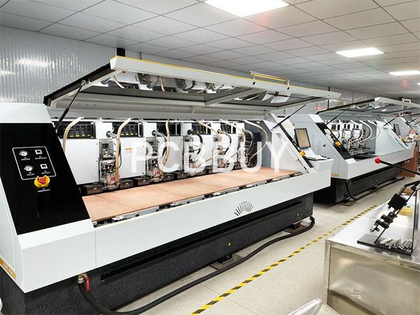
Drilling is a slow process as each hole must be drilled individually. So depending on the drill size we drill a stack of one to three PCB panels together. We can drill holes down to 100 microns in diameter. To give you an idea of the size, the diameter of a human hair is about 150 microns. Drill change is fully automatic. The machine selects the drill to use from the drill rack, checks that it is the correct size, and then loads it into the drill head.
X-ray drill of reference holes
Now we drill the holes for leaded components and the via holes that link the copper layers together. First we use an X-ray drill to locate targets in the copper of the inner layers. The machine drills registration holes to ensure that we will drill precisely through the centre of the inner layer pads.
Prepare the stacks for drillng
To set up the drill the operator first puts a panel of exit material on the drill bed. This stops the drill tearing the copper foil as it comes through the PCB. Then he loads one or more PCB panels, and a sheet of aluminium entry foil.
Drilling the holes
The drilling machine is computer-controlled. The operator selects the right drill program. This tells the machine which drill to use and the X Y co-ordinates of the holes. Our drills use air-driven spindles which can rotate up to 150,000 revolutions per minute. High speed drilling ensures clean hole walls to provide a secure base for good plating on the hole walls.
Once all the holes are drilled the operator unloads the panels from the drilling machine and discards the entry and exit material.
Different holes of PCB drilling
A raw circuit board can have many fabricated properties, including cut-outs, slots, and the finished board’s overall shape. The largest number of such properties will be the holes that are drilled into the board. The purpose of these holes can be broken down into three categories:
Via Holes
Small holes plated with metal are used to conduct electrical signals, power, and ground through the board layers. These holes are known as vias, and they come in different types depending on what is required:
Thru-hole: This is the standard via, and it goes through the entire board layer stackup from top to bottom. These vias can connect to traces or planes on as many internal layers as needed.
Buried: These vias start and stop on internal board layers without extending to an external layer. This structure takes much less room than a standard thru-hole via, making them very useful in high-density interconnect (HDI) circuit boards. However, they are also much more expensive to fabricate.
Blind: A blind via starts on an external layer but only goes partway through the board. As with buried vias, they are more expensive to fabricate, but they free up room for routing, and their shorter barrel can also help improve the signal integrity of high-speed transmission lines.
Micro: This via has a smaller hole size than the others because it’s drilled with a laser. Microvias are usually only two layers deep due to the difficulties of plating smaller holes. These vias are necessary for HDI boards or high pin-count fine-pitch devices like BGAs that require their escape vias to be put into their solder pads.
Component holes
While surface mount parts are used for most active and discrete components on circuit boards today, many parts are still preferable to use with a thru-hole package. These components are typically connectors, switches, and other mechanical parts that need the more robust mounting that a thru-hole package provides. Additionally, thru-hole packages are usually preferred for power components such as large resistors, capacitors, op-amps, and voltage regulators due to the current and heat conduct.
Mechanical holes
A circuit board will usually have mechanical features or objects attached to it, such as brackets, connectors, or fans, which require holes for mounting. Although these holes are generally not plated with metal, they can be if the mounted feature requires an electrical connection to the board, such as chassis ground. In some cases, mounting holes are used to disperse the hot components’ heat to the inner plane layers. Another purpose of mechanical holes is to aid in the manufacturing of the board. These holes are often referred to as “tooling holes.” They are used to align the board on automated manufacturing equipment.
Those are the different holes in the board that require drilling.
Industry Category


