Insulated Metal Substrate PCB for Automotive LED Driver
By:PCBBUY 10/27/2026 14:33
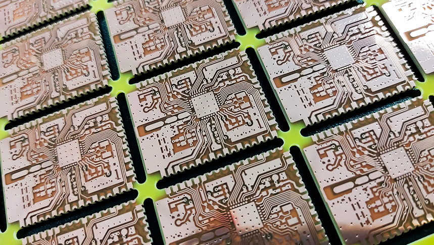
Automotive LED drivers must deliver stable current while operating under demanding thermal, electrical, and environmental conditions. In high-power lighting systems such as LED headlamps and exterior lighting modules, heat management is essential for maintaining light output, controlling component temperature, and supporting long-term reliability.
An insulated metal substrate PCB for automotive LED driver applications can provide an effective thermal path by combining a copper circuit layer, an electrically insulating dielectric layer, and a metal base. However, the right PCB structure depends on whether the board primarily supports high-power LEDs, switching power electronics, or both.
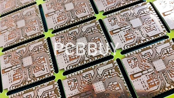
1. How Does an Insulated Metal Substrate PCB Work?
An insulated metal substrate (IMS) PCB, also called a metal core PCB (MCPCB), typically consists of three main layers:
-
Copper circuit layer: Carries electrical current and connects components.
-
Dielectric insulation layer: Electrically isolates the copper circuit from the metal base while transferring heat.
-
Metal base: Usually aluminum, which spreads heat and provides mechanical support.
The metal base helps conduct heat away from power components toward the chassis or heat sink. The dielectric layer is especially important because its thermal resistance affects the overall heat path, while its dielectric strength must meet the electrical isolation requirements.
For automotive LED driver designs, an IMS board can be suitable for high-power LED arrays or thermally demanding circuits. However, complex driver electronics may require multilayer FR-4 or high-Tg PCB structures to accommodate control circuits, switching components, and routing requirements. The optimal architecture should be selected according to the complete electrical and thermal design.
2. Key Advantages for Automotive LED Driver Applications
|
Design requirement |
IMS PCB advantage |
Engineering consideration |
|
Heat dissipation |
Conducts heat toward the metal base and external cooling structure |
Evaluate the complete thermal path, including dielectric, base plate, interface material, and heat sink |
|
Electrical isolation |
Dielectric separates copper circuitry from the metal base |
Verify dielectric thickness, breakdown requirements, and operating voltage |
|
Mechanical support |
Metal base provides rigidity and heat spreading |
Assess board flatness, mounting, vibration, and thermal expansion |
|
Long-term reliability |
Better thermal management can help reduce component temperature |
Validate temperature cycling, solder-joint stress, and actual operating conditions |
|
Compact lighting design |
Supports thermally demanding LED layouts |
Confirm routing space, current paths, assembly access, and cooling constraints |
IMS technology does not automatically guarantee longer LED life or eliminate thermal problems. LED junction temperature, driver efficiency, cooling design, component selection, and operating conditions all contribute to system reliability.
3. PCB Layout Considerations for Automotive LED Drivers
Design current paths and switching loops carefully
For switching LED drivers, keep high-current loops compact and minimize unnecessary trace length. Place input bypass capacitors close to the relevant power-stage connections, and separate sensitive feedback or control signals from noisy switching nodes where practical.
Trace width and copper thickness should be selected based on current, allowable voltage drop, temperature rise, and manufacturing capability. Do not rely on a generic trace-width rule alone; verify the design using suitable calculations and thermal analysis.
Optimize the thermal path
Identify the components generating the most heat and ensure that the heat can move efficiently through the PCB and into the cooling structure. For IMS designs, dielectric thermal resistance and thickness are key factors. Mechanical mounting and the interface between the metal base and heat sink can also significantly affect thermal performance.
Consider automotive operating conditions
Automotive lighting can experience temperature cycling, vibration, moisture exposure, and electrical transients. The PCB layout, materials, solder joints, and insulation system should be selected according to the vehicle program's requirements. Applicable automotive qualification and validation must be confirmed for the specific product; the use of an IMS PCB alone does not establish compliance.
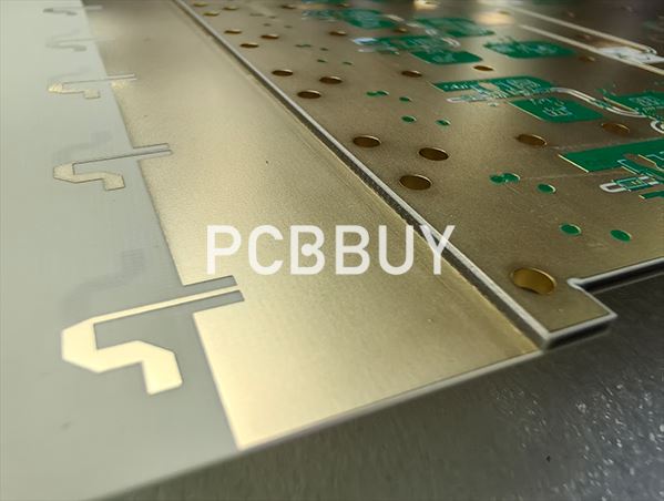
4. Material Selection and Manufacturing Quality
PCBBUY's published manufacturing information includes metal core PCB and aluminum PCB solutions for LED lighting and thermal-management applications. These options can be evaluated for automotive LED projects according to board geometry, copper requirements, dielectric properties, and thermal design.
During engineering review, customers should confirm the following:
-
Metal base material and thickness.
-
Copper thickness and required conductor geometry.
-
Dielectric thermal properties, thickness, and electrical isolation requirements.
-
Surface finish and compatibility with the intended SMT assembly process.
-
Board dimensions, flatness, mounting features, and dimensional tolerances.
PCBBUY also provides conventional multilayer PCB manufacturing and selected high-Tg and high-frequency material options. These capabilities may be relevant when a project uses separate IMS LED boards and FR-4 driver-control boards, or when the electrical architecture requires a different PCB construction.
5. Inspection, Testing, and Shipment Acceptance
Quality requirements should be defined before production. Depending on the design and customer specification, relevant checks may include:
|
Quality check |
Purpose |
|
Visual and dimensional inspection |
Verifies board appearance, outline, and specified dimensions |
|
Copper and dielectric verification |
Checks construction against the approved material and thickness requirements |
|
Electrical testing |
Checks circuit continuity and isolation as applicable |
|
Insulation or dielectric withstand testing |
Verifies electrical isolation when required by the design specification |
|
Flatness and assembly review |
Helps assess mounting and component-placement suitability |
|
Thermal validation |
Evaluates thermal performance under representative operating conditions when required |
PCBBUY's published quality processes include AOI and electrical testing, while project-specific tests should be confirmed during quotation and engineering review. Thermal performance, dielectric withstand, and automotive qualification tests should not be assumed to be included in every order.
Shipment acceptance should follow the approved fabrication data, purchase order, applicable IPC requirements, and customer-specific criteria. For automotive projects, any required traceability, qualification records, or additional reliability testing should be agreed upon before production.
Conclusion
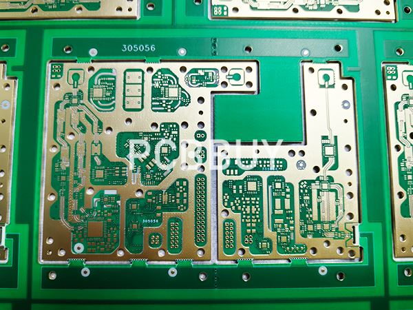
An insulated metal substrate PCB can be a practical solution for automotive LED driver applications where heat dissipation, electrical isolation, and mechanical support are important. Reliable results depend on more than the metal base: dielectric performance, copper design, thermal interfaces, switching-loop layout, and application-specific validation all matter.
PCBBUY's metal core PCB and aluminum PCB manufacturing options provide a starting point for evaluating thermally demanding LED designs. By sharing the complete stackup, electrical requirements, thermal targets, and automotive acceptance criteria early, customers can work with the engineering team to assess manufacturability and select an appropriate PCB structure.
FAQ
1. What is an insulated metal substrate PCB for automotive LED drivers?
It is a PCB structure that typically combines a copper circuit layer, a dielectric insulation layer, and a metal base—usually aluminum—to help transfer heat away from LED or power components while maintaining electrical isolation.
2. Why is an IMS PCB useful for automotive LED lighting?
It can provide an efficient heat-spreading path and mechanical support for thermally demanding LED assemblies. Actual performance depends on the dielectric, copper design, cooling structure, and operating conditions.
3. Can an IMS PCB replace FR-4 in every LED driver?
No. IMS is often suitable for high-power LED boards, but complex driver electronics may need multilayer FR-4 or high-Tg boards for routing, control circuitry, and component integration. The choice depends on the system architecture.
4. What should I check when selecting an IMS PCB manufacturer?
Confirm the manufacturer's capabilities for metal base processing, dielectric material selection, copper thickness, dimensional control, electrical testing, and any required thermal or insulation validation. Automotive-specific qualification requirements should be confirmed separately.
5. What information is needed for an accurate IMS PCB quotation?
Provide the Gerber files, board dimensions, copper thickness, metal base material and thickness, dielectric requirements, surface finish, quantity, thermal targets, electrical isolation requirements, and applicable customer acceptance criteria.
Industry Category