What Are the Main Properties of Copper Clad Laminate (CCL) PCB?
By:PCBBUY 04/11/2024 17:11
 PCB?")
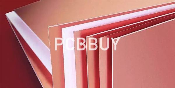
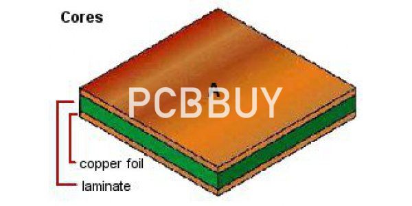
Copper Clad Laminate (CCL) in rigid boards, also called PCB laminate, is a type of substrate material of printed circuit boards with a thin layer of copper laminated on either one side or both sides, and we call it as single-sided CCL or double-sided CCL. In rigid PCB production, manufacturers use rigid CCLs with substrate material, like resin epoxy (FR4), metal core, PTFE and Ceramic, to fabricate single-, double- and multi-layer circuit boards.
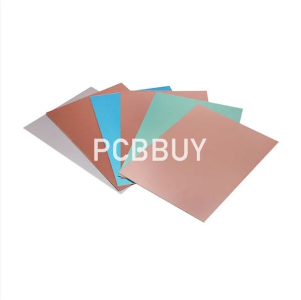
What Are the Properties in Different Substrate?
Resin Epoxy FR-4 CCL
FR-4 (or FR4) copper clad laminate (CCL) is a rigid PCB substrate material with copper clad on either one side or both sides of FR4 base, which is a composite material composed of woven fiberglass cloth with an epoxy resin binder that is flame resistant. FR stands for flame retardant, and does not denote that the material complies with the standard UL 94V-0 unless testing is performed to UL 94, Vertical Flame testing in Section 8 at a compliant lab. The designation FR-4 was created by NEMA (National Electrical Manufacturers Association) in 1968.
Properties of FR-4 CCL:
· Low Glass Transition Temperature (Tg) (Tg130 oC – Tg140 oC)
· Mid Glass Transition Temperature (Tg) (Tg150 oC)
· High Glass Transition Temperature (Tg) (Tg170oC)
· High Decomposition Temperature (Td) (Td>345oC)
· Dielectric Constant (Dk or Er) (@1GHz): 3.66-4.5
· Dissipation Factor (Df) (@1GHz): 0.016
· High UL Rated Flammability: 94V-0
· Low Coefficient of Thermal Expansion (CTE) (2.5%-3.8%)
· High Comparative Tracking Index (CTI): (CTI >=600V)
· Halogen-free
· Compatible with standard and lead-free assembly
· FR4 CCL thickness available from 0.2mm to 3.2mm
· Copper thickness available form 1/3oz to 3oz
Aluminum Core CCL
Aluminum (Aluminium or Alu) core or Aluminum base copper clad laminate (CCL) is made of aluminum board, dielectric bonding layer and copper foil by high temperature and hot pressing. The metal layers are with high thermal conductivity, while the overall conductivity of the Aluminum core laminate is decided by the dielectric bonding layer. With high thermal conductivity, the dielectric may be filled with ceramic.
Most aluminum PCB boards are built with single-sided CCL, while double-sided CCL for double-sided Aluminum PCB and multilayer hybrid Aluminum PCB manufacturing are possible at.
Properties of Aluminum Core CCL:
· Thermal Conductivity: 1.0W/m·K, 1.5W/m·K, 2.0W/m·K, 3.0W/m·K, 4.2W/m·K, 5.0W/m·K, 7.0W/m·K
· Aluminum (Al) Alloy Style: 1060 (138 W/m·K) and 5052 (220 W/m·K)
· Copper (Cu) Style: C1100 (386 W/m·K)
· Copper thickness available from 0.5oz to 2oz
· Glass Transition Temperature (Tg): Tg100oC, Tg120oC, Tg130oC
· Dielectric Constant (Dk or Er) (@1MHz): 4.8
· Halogen-free
· Compatible with standard and lead-free assembly
· High UL Rated Flammability: 94V-0
· Aluminum Core CCL thickness available from 0.8mm to 2.0mm
Copper Core CCL
Similar to Aluminum Core CCL, Copper Core CCL is made of copper board, dielectric bonding layer and copper foil. The thermal conductivity is mainly decided by the bonding dielectric layer and whether your board has thermal dissipation design.
Copper Core PCB, also referred to copper substrate PCB, copper based PCB or copper clad PCB, which has 3 main design types:
· Common copper core PCB: (with circuitry on copper layer without PTH)
· Chip on Board (COB) copper PCB
· Direct thermal path copper-based PCB (no insulator under the thermal path pad)
Properties of Copper Core CCL:
· Thermal Conductivity: 3.0W/m·K, 5.0W/m·K, 7.0W/m·K
· Copper (Cu) Style: C1100 (386 W/m·K)
· Copper thickness available from 0.5oz to 2oz
· Glass Transition Temperature (Tg): Tg100oC, Tg120oC, Tg130oC
· Dielectric Constant (Dk or Er) (@1MHz): 4.8
· Halogen-free
· Compatible with standard and lead-free assembly
· High UL Rated Flammability: 94V-0
· Copper Core CCL thickness available from 0.8mm to 2.0mm
Radio Frequency (RF) /Microwave PCB CCL
When your PCB boards designed at microwave frequencies, the key characteristics that define CCL and prepreg (PP) performance for microwave/RF printed circuit boards include dielectric constant (Dk), dissipation factor (Df), coefficient of thermal expansion (CTE), thermal coefficient of dielectric constant (TCDR), and thermal conductivity.
The high-frequency material perhaps most familiar to designers and manufacturers is PTFE (Polytetrafluoroethylene), which is a synthetic thermoplastic fluoropolymer that has excellent dielectric properties at microwave frequencies. Below is a brief outline of the major material suppliers that we have experience with as every material is processed a bit differently and it is critical to know exactly how the materials will respond to every process.
There are 4 copper clad laminate companies manufacture high-frequency materials:
Isola High Performance PCB laminates: since their founding in 1912, Isola has been the industry leader in developing and manufacturing copper-clad laminate products used to fabricate advanced multilayer printed circuit boards (PCBs).
Properties of Copper Clad Laminate
The properties of Copper Clad Laminate in PCBs include the following:
Electrical Conductivity: The copper layer on the CCL provides excellent electrical conductivity for efficient signal transmission.
Thermal Conductivity: Copper is a good conductor of heat, dissipating heat that generates during the operation of the PCB.
Mechanical Strength: The fiberglass base material provides mechanical stability, helping to protect the PCB from damage and ensuring its longevity.
Chemical Resistance: CCL has good resistance to chemicals, making it suitable for use in harsh environmental conditions.
Thermal Stability: CCL has high thermal stability, allowing it to maintain its structural integrity under extreme temperatures.
Flexibility: CCL is flexible, making it suitable for applications where the PCB may be subject to stress or strain.
Surface Finish: The surface of the CCL is smooth and uniform, providing a high-quality finish for the PCB.
How to Process Electrical Performance Test of Copper-clad Laminates (CCL)?
The electrical properties of copper-clad laminates(CCL) mainly include surface resistivity and volume resistivity, dielectric constant and dielectric loss Angle tangent value, insulation resistance and electrical strength. Because the electrical properties of the foil-covered board decrease significantly with the increase of temperature and humidity, the national standard stipulates that the electrical properties of the foil-covered board are measured under constant temperature and humidity, after constant temperature and humidity treatment and hot state respectively.
Surface resistivity and volume resistivity tests
A square board with a side length of 100mm±1mm was cut from the foil board, and the sample was prepared according to the standard figure. If it is a double-sided foil board, one side of the copper foil should be etched off. Surface resistivity and volume resistivity can be measured on the same sample, using a three-electrode system, with a small amount of medical vaseline or silicone grease, annealed aluminum foil or tin foil electrode with a thickness of no more than 0.02mm on the sample substrate surface for testing, and no air gaps and impurities are allowed during testing.
The measurement of surface resistivity and volume resistivity under constant temperature and humidity is to place the pre-treated sample with the measured thickness in an environment with a temperature of (40±2)℃ and a relative humidity of 90%~95%, and to measure it in a hot and humid chamber after 96h.
The surface resistivity and volume resistivity measurement after constant temperature and humidity recovery is to take the sample after constant temperature and humidity treatment from the wet heat box and put it in the controlled condition to recover for (90±15)min. The measurement of surface resistivity and volume resistivity in hot state is to place the pre-treated and thick-measured sample in a specified hot state environment for 60~66min, and then determine it in hot state. Testers should wear clean rubber gloves, and finger contamination can reduce surface resistivity by two orders of magnitude or more.
The surface resistivity and volume resistivity were measured by the insulation resistance measuring instrument, the test voltage was (500±50)V, and the reading was made after 1min of energizing.
Dielectric strength of 1.6mm thick CCL PCB substrate
|
NEMA |
XXXP |
FR2 |
FR3 |
G10 |
G11 |
FR4 |
FR5 |
Polyimide |
|
Dielectric strength(kV/mm) |
29 |
29 |
21 |
20 |
23 |
19 |
19 |
19 |
Dielectric Constant and Dielectric Loss Angle Tangent Value Test
Samples with a width of (80±1)mm, a length of 80~100mm and a thickness of the board were cut from the foil-covered board, and the copper foil was etched off. After pretreatment and constant temperature and humidity treatment for 90h, the samples were measured in a wet heat chamber. Or take it out of the wet heat box and restore it for (90±15) minutes. An annealed aluminum foil electrode not exceeding 0.02mm thick is affixed to the sample using a minimal amount of medical Vaseline or silicone grease. The aluminum foil electrode size is the same as the surface size of the sample, measured at 1MHz with a Q-meter or other appropriate measuring instrument.
Insulation Resistance Test Insulation Resistance Test
It is to pass the DC current between the two electrodes of the sample, measure the leakage current of the sample with the insulation resistance meter, and then calculate the insulation resistance. Cut a sample with length of (40±2)mm, width of (20±1)mm and thickness of the board from the foil-covered board, etch off the copper foil, drill two holes in the middle of the sample, the two holes have the same taper direction, and the hole center distance is (15±0.25)mm.
After the sample is pretreated according to the standard, A cone-pin electrode with a diameter of 5mm and a taper of 2% is installed in copper or steel, and the sample extending from the electrode end is not less than 2mm. Insulation resistance of parallel layer was measured by insulation resistance meter. The test voltage is (500±50)V, and the reading is expressed in megohm after 1min of power-on.
Electrical Strength test Electrical Strength Test
Used to determine the ability of the substrate to withstand voltage breakdown in the direction perpendicular to the surface of the board for a short time, only applicable to the thickness of <0.5mm foil-covered board. Cut a square with a side length of (100±1)mm from the foil board and etch off the copper foil. Electrodes made of copper or steel are bonded on both sides of the substrate and tested in the air by 20s stepwise voltage method until breakdown.
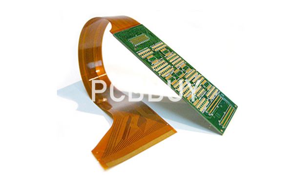
What is the Development Trend of Flexible CCL?
Flexible CCLs have witnessed a wide application field in the future. Simultaneously, much progress has been made on new types of flexible CCLs by researchers, such as high-Tg flex CCL, halogen-free and phosphor-free flex CCL, high-speed flex CCL and ultra-thin flex CCL.
• High-Tg Flex CCL. As far as 3L-FCCL is concerned, the key point of high-Tg flex CCL lies in heat resistance improvement of adhesive. Adhesive applied in 3L-FCCL is now primarily epoxy resin and acrylic acid. As a result, high-Tg flex CCL has to keep manufacturing cost as low as possible with dimensional stability, insulation and chemical resistance first ensured.
• Halogen-Free and Phosphor-Free Fire-Resistance Flex CCL. Due to EU regulations release and people's calling for environmental protection, halogen-free and phosphor-free have become the new development target of flex CCLs.
• High-Speed Flex CCL. Recent years have seen high frequency and high speed of signal transmission so that new need in terms of high frequency and high speed has been called for.
• Ultra-Thin Flex CCL. Light weight demand of electronic products has scattered around flex CCLs, which is the leading reason for ultra-thin flex CCLs.
Reference
He Wei, PCB Basic Electrical Information Science and Technoloy, China Machine Press,26-29
Industry Category


